Chapter 5 Installing the Open Telecommunications Platform Using the Graphical User Interface
This chapter provides the procedures for using the OTP provisioning service graphical user interface on an external OTP installation server to install and configure Open Telecommunications Platform to your clustered OTP systems.
The following topics are discussed:
-
Graphical User Interface Installation and Configuration Overview
-
Installing the Open Telecommunications Platform On A Standalone OTP Host
-
Installing the Open Telecommunications Platform On A Clustered OTP System
Graphical User Interface Installation and Configuration Overview
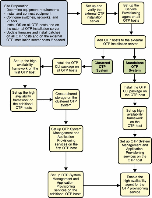
The following figure provides a summary of the high-level tasks that you will perform as part of the GUI-based Open Telecommunications Platform installation and configuration processes.
The following diagram illustrates the sequence of the high-level tasks for site planning, installation and configuration of the Open Telecommunications Platform.
Figure 5–1 GUI-Based Open Telecommunications Platform Installation Task Flow
Summaries of each of the above graphical user interface install tasks are provided in the following list.
-
Site Preparation
This task involves the following actions:
-
Inventory the equipment you want to use with the Open Telecommunications Platform, and compare the inventory to the system requirements in as described in OTP System Hardware and Firmware Requirements.
-
Open Telecommunications Platform Prerequisites
The following prerequisites must be met before you can install the Open Telecommunications Platform using the External OTP installation server graphical user interface.
-
Solaris 10 Update 2 must be installed and configured on each clustered OTP system server as described in Installing and Configuring Solaris 10 Update 2 Operating System.
-
NIS setup must be completed on all clustered OTP system servers.
-
All clustered OTP system serverss and storage devices must meet the minimum patch and firmware requirements as described in OTP System Plan Settings Descriptions.
-
The Solaris 10 Update 2 operating system must be installed and configured on the external OTP installation server as described in Installing and Configuring Solaris 10 Update 2 Operating System.
Preparing for Installation
This section provides the procedures for preparing the external OTP installation server and the clustered OTP hosts for Open Telecommunications Platform installation.
The preparation process is comprised of the following procedures, which must be performed in sequence.
 To Set Up and Verify the External OTP Installation Server
-
Log in as root (su - root) to the external OTP installation server.
-
If the external OTP installation server is the same server to which you downloaded the Open Telecommunications Platform software, go to Step 2.
-
If the external OTP installation server is not the same server to which you downloaded the Open Telecommunications Platform software, perform the following steps.
-
Copy the entire Open Telecommunications Platform installation directory from the download server or from the OTP Installation DVD-ROMto the external OTP installation server.
The download server is the server to which you downloaded the Open Telecommunications Platform product in To Download and Uncompress the OTP and Solaris OS Installation Zip Files. :
For example:
-
If your download server name is downloads
-
You have moved the unzipped OTP install directory to /otp1.0
-
You have NFS-mounted the /otp1.0 directory on the download server
You would then type:
# cp -r /net/downloads/otp1.0 /otp1.0
-
-
Add the following line to the /etc/dfs/dfstab file.
share -F nfs -o ro,log=global -d "OTP 1.0 Installation Directory" /otp1.0
Note –The /otp1.0 directory is referred to throughout this document as the OTP installation directory.
-
Type svcadm restart nfs/server to stop and then restart NFS and NFS-mount the installation directory.
-
-
Type pkgadd -d /otp1.0/Products/packages -R / SUNWotpcli
The directory /opt/SUNWotp10/CLI is created.
-
Set up the external OTP installation server.
Type /opt/SUNWotp10/CLI/setupExternalInstallServer /otp1.0
The installation process installs the OTP application provisioning service and the Open Telecommunications Platform plug-in.
Wait for the installation process to complete. The installation process may take up to 10 minutes to complete.
-
Open a Web browser.
Go to URL http://install server:9090 where install server is either the IP address or the fully qualified name of the external OTP installation server.
If installation was successful, the service provisioning system log in page appears.
-
(Optional) Click change password and change the password on the next page.
Type the default user name and password admin in the user name: and current password: fields.
Type the new password in the new password: and confirm new password: fields, and then click continue to change password.
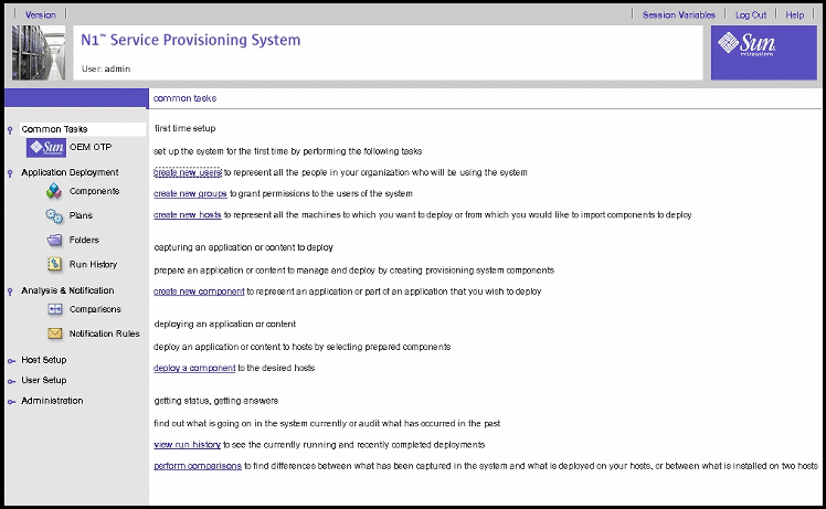
The log in page appears. Log in to the service provisioning system. The Common Tasks page appears.
Figure 5–2 Common Tasks Page
-
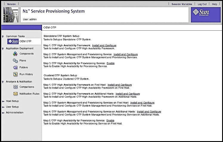
Click OEM OTP under Common Tasks in the left menu to display the Open Telecommunications Platform home page.
Figure 5–3 Open Telecommunications Platform Tasks Page
-
Click Plans under Application Deployment to display the plans screen.
Figure 5–4 Plans Screen
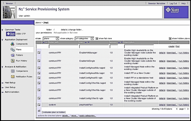
Successful display of the screens verifies installation of the service provisioning system and the Open Telecommunications Platform plug-in.
-
Next Steps
Set up the service provisioning remote agent on the clustered OTP systems as described in the next procedure.
 To Set Up the Service Provisioning Remote Agent on the Clustered OTP Systems
The service provisioning remote agent must be installed on the standalone OTP host for a standalone OTP system, and on each clustered OTP host for a clustered OTP system. The remote agent must be installed on each OTP host for Open Telecommunications Platform installation to succeed..
Perform the following steps for each new OTP host
Before You Begin
The external OTP installation server must be set up and verified as described in Preparing for Installation.
-
Log in as root (su - root) to the new OTP host.
-
Install the OTP CLI package.
Type pkgadd -d /net/external OTP installation server/otp1.0/Products/packages -R / SUNWotpcli where external OTP installation server is the name of the external OTP installation server.
For example, if the installation server name is otpinstall, you would then type:
# pkgadd -d /net/otpinstall/otp1.0/Products/packages -R / SUNWotpcli
The directory /opt/SUNWotp10/CLI is created.
-
Install the service provisioning remote agent.
Type /opt/SUNWotp10/CLI/setupRemoteAgent install directory where install directory is the Open Telecommunications Platform installation source directory. For example:
# /opt/SUNWotp10/CLI/setupRemoteAgent /net/otpinstall/otp1.0-install
The setupRemoteAgent script creates the service provisioning user account and installs the remote agent.
Next Steps
Add each new OTP host to the external OTP installation server as described in the next section.
 To Add Hosts to the External OTP Installation Server
Before you can install the Open Telecommunications Platform to the standalone OTP host or to the clustered OTP hosts, you must add each host to the host list on the external OTP installation server. Perform the following steps for each new OTP host.
Before You Begin
-
The external OTP installation server must be set up and verified as described in Preparing for Installation.
-
The service provisioning remote agent must be installed on all of the clustered OTP system hosts as described in To Set Up the Service Provisioning Remote Agent on the Clustered OTP Systems
-
Open a Web browser and log in to the external OTP installation server service provisioning service.
Go to URL http://install server:9090 where install server is either the IP address or the fully qualified name of the external OTP installation server.
-
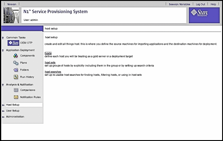
Click Host Setup in the left menu to display the Host Setup page:
Figure 5–5 Host Setup page
-
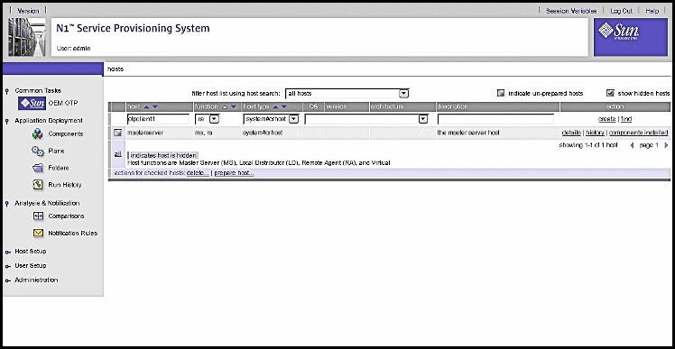
Click hosts in the central menu to display the hosts page:
Figure 5–6 Hosts Page
-
In the host field, type the name of the new OTP host.
-
(Optional) In the description field, type a description of the new OTP host.
-
Click create.
The host details edit page is displayed as shown in the next step.
-
-
Specify the host values on the details edit page:
Figure 5–7 Host Edit Details Page
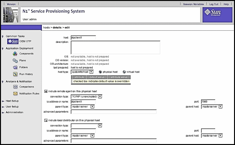
Note –The above example of the host edit details page shows only the required fields at the top of the page.
-
Click include remote agent on this physical host
-
Click the arrow to the right of the connection type field to display the drop-down list.
Choose TCP/IP (unencrypted).
-
In the ip address or name field, type either the IP address of the host or the host name.
-
In the port field, type 7000.
-
Scroll to the bottom of the page and click save.
The host is added to the hosts list on the external OTP installation server. The hosts list page is displayed.
-
Check the box to the left of the host name, and then click prepare host...
The host is prepared for provisioning.
-
Next Steps
Repeat this procedure for every host to which the Open Telecommunications Platform is to be installed. When you have finished adding all hosts to the external OTP installation server hosts list:
-
If you are installing the Open Telecommunications Platform to a standalone OTP host, install the Open Telecommunications Platform as described in Installing the Open Telecommunications Platform On A Standalone OTP Host.
-
If you are installing Open Telecommunications Platform to a clustered OTP system, install the Open Telecommunications Platform as described in Installing the Open Telecommunications Platform On A Clustered OTP System.
Installing the Open Telecommunications Platform On A Standalone OTP Host
In a standalone OTP host, the single host is the first OTP host server for the cluster.
Graphical user interface installation and setup of the Open Telecommunications Platform on a standalone OTP host is comprised of the following procedures:
Note –
Refer to the OTP System Plan Settings Descriptions and the Standalone OTP Host Plan Worksheet for information needed during installation.
 To Set Up the OTP High Availability Framework
The OTP high availability framework must be set up on the standalone OTP host.
Before You Begin
-
The external OTP installation server must be set up and verified as described in To Set Up and Verify the External OTP Installation Server
-
The Service Provisioning remote agent must be set up on the standalone OTP host as described in To Set Up the Service Provisioning Remote Agent on the Clustered OTP Systems
-
The standalone OTP host must be added to the external install server as described in To Add Hosts to the External OTP Installation Server
-
Open a Web browser and log in to the external OTP installation server service provisioning service.
Go to URL http://install server:9090 where install server is either the IP address or the fully qualified name of the external OTP installation server.
-
Click OEM OTP to display the Open Telecommunications Platform home page.
-
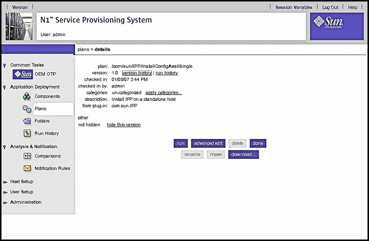
Click Step 1. OTP High Availability Framework: Install and Configure
The edit availability plan page appears.
Figure 5–8 Edit Availability Plan Page
-
Click run.
The Availability Plan Variables page appears.
Figure 5–9 Availability Plan Variables Page
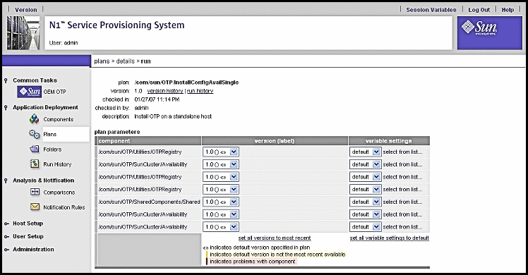
Scroll the page down to view the variables:
Figure 5–10 Availability Plan Variables Page: Variables
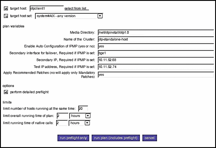
Type the information in the plan variables fields according to your Standalone OTP Host Plan Worksheet. Refer to the OTP System Plan Settings Descriptions for information about each variable.
 Caution –
 Set limit overall running time of plan and limit running time of native calls to 2 hours each.
-
Click run plan (includes preflight).
The page refreshes, and a progress bar is displayed during the provisioning process.
The provisioning process:
-
Installs required Solaris OS patches
-
Installs the OTP high availability framework
-
Configures the standalone OTP host
-
Reboots the standalone OTP host
-
Verifies the OTP high availability framework configuration
-
Next Steps
Set up the system management and provisioning services on the standalone OTP host as described in the following procedure.
 To Set Up OTP System Management and Provisioning
Services
Before You Begin
The OTP high availability framework must be set up on the standalone OTP host as described in the previous procedure.
-
Open a Web browser and log in to the external OTP installation server service provisioning service.
Go to URL http://install server:9090 where install server is either the IP address or the fully qualified name of the external OTP installation server.
-
Click OEM OTP to display the Open Telecommunications Platform home page.
-
Click Step 2. OTP System Management and Provisioning Service: Install and Configure.
The edit System Management and Application Provisioning plan page appears.
-
Click run.
The Availability Plan Variables page appears. Scroll the page down to display the variables
Figure 5–11 System Management and Application Provisioning Plan Variables Page
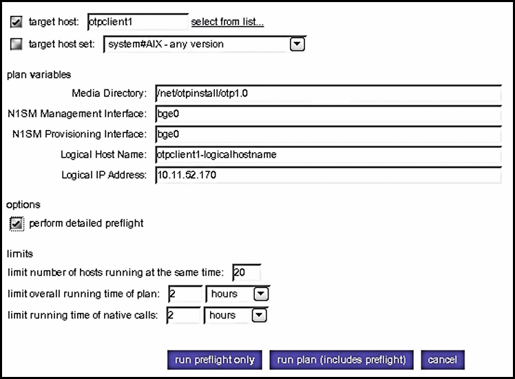
Type the information in the plan variables fields according to your Standalone OTP Host Plan Worksheet. Refer to the OTP System Plan Settings Descriptions for information about each variable.
 Caution –
 Set limit overall running time of plan and limit running time of native calls to 2 hours each.
-
Click run plan (includes preflight).
The page refreshes, and a progress bar is displayed during the provisioning process.
The provisioning process:
-
Installs the Web console
-
Applies patches required by the Open Telecommunications Platform
-
Installs the system management service
-
Installs the service provisioning service
-
Installs Java patches
When the provisioning process completes, click done.
-
Next Steps
Enable high availability on the standalone OTP host as described in the following procedure.
 To Enable High Availability For the OTP Provisioning Service
Before You Begin
OTP System management and provisioning services must be set up on the standalone OTP host as described in the previous procedure.
-
Open a Web browser and log in to the external OTP installation server service provisioning service.
Go to URL http://install server:9090 where install server is either the IP address or the fully qualified name of the external OTP installation server.
-
Click OEM OTP to display the Open Telecommunications Platform home page.
-
Click Step 3. OTP High Availability for Provisioning Service: Enable .
The edit High Availability plan page appears.
-
Click run.
The High Availability Plan Variables page appears. Scroll the page down to display the variables
Figure 5–12 High Availability Plan Variables Page
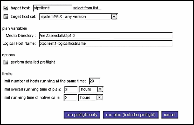
Type the information in the plan variables fields according to your Standalone OTP Host Plan Worksheet. Refer to the OTP System Plan Settings Descriptions for information about each variable.
 Caution –
 Set limit overall running time of plan and limit running time of native calls to 2 hours each.
-
Click run plan (includes preflight).
The page refreshes, and a progress bar is displayed during the provisioning process.
The provisioning process installs and enables the application provisioning service high availability agent.
When the provisioning process completes, click done.
-
Log in as root to the standalone OTP host and restart the remote agent.
Type /etc/init.d/n1spsagent restart to restart the remote agent. If the remote agent is not restarted, then the service provisioning service on the standalone OTP host will not work properly.
This completes installation of the Open Telecommunications Platform on a standalone OTP host.
Installing the Open Telecommunications Platform On A Clustered OTP System
Graphical user interface installation and setup of the Open Telecommunications Platform on a clustered OTP system is comprised of the following steps:
-
To Set Up the OTP High Availability Framework on the First OTP Host
-
To Set Up the OTP High Availability Framework on the Additional OTP Hosts
-
To Set Up OTP System Management and Provisioning Services on the First OTP Host
-
To Set Up OTP System Management and Provisioning Services on the Additional OTP Hosts
-
To Enable High Availability for the OTP Provisioning Service on the First OTP Host
Note –
Refer to the OTP System Plan Settings Descriptions and the Clustered OTP Host Plan Worksheet for information needed during installation.
 To Set Up the OTP High Availability Framework on the First OTP Host
Availability services must first be set up on the first OTP host in your clustered OTP system.
Before You Begin
-
The first OTP host must be connected to shared storage
-
The external OTP installation server must be set up and verified as described in To Set Up and Verify the External OTP Installation Server
-
The Service Provisioning remote agent must be set up on all hosts in the clustered OTP system as described in To Set Up the Service Provisioning Remote Agent on the Clustered OTP Systems
-
All hosts in the clustered OTP system must be added to the external OTP installation server hosts list as described in To Add Hosts to the External OTP Installation Server
-
Open a Web browser and log in to the external OTP installation server service provisioning service.
Go to URL http://install server:9090 where install server is either the IP address or the fully qualified name of the external OTP installation server.
-
Click OEM OTP to display the Open Telecommunications Platform home page.
-
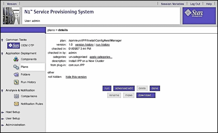
Click Step 1. OTP High Availability Framework on First Host: Install and Configure.
The edit availability plan page appears.
Figure 5–13 Clustered OTP Host Edit Availability Plan Page: System Management Server
-
Click run.
The Availability Plan Variables page appears. Scroll the page down to view the variables:
Figure 5–14 Clustered OTP Host Availability Plan Variables Page: System Management Server Variables
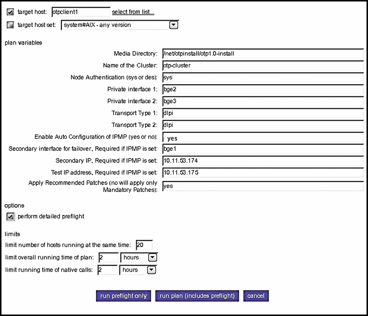
Type the information in the plan variables fields according to your Clustered OTP Host Plan Worksheet. Refer to the OTP System Plan Settings Descriptions for information about each variable.
 Caution –
 Set limit overall running time of plan and limit running time of native calls to 2 hours each.
-
Click run plan (includes preflight).
The page refreshes, and a progress bar is displayed during the provisioning process.
The provisioning process:
-
Installs required Solaris OS patches
-
Installs the OTP high availability framework
-
Configures the first OTP host
-
Reboots the first OTP host
-
Verifies the first OTP host configuration
-
Next Steps
Set up availability services on the additional OTP hosts as described in the next procedure.
 To Set Up the OTP High Availability Framework on the Additional OTP Hosts
The OTP high availability framework must be set up on each host in your clustered OTP system. Perform the following steps on each host.
Before You Begin
The OTP high availability framework must be set up on the First OTP Host as described in the previous procedure.
-
Open a Web browser and log in to the external OTP installation server service provisioning service.
Go to URL http://install server:9090 where install server is either the IP address or the fully-qualifed name of the external OTP installation server.
-
Click OEM OTP to display the Open Telecommunications Platform home page.
-
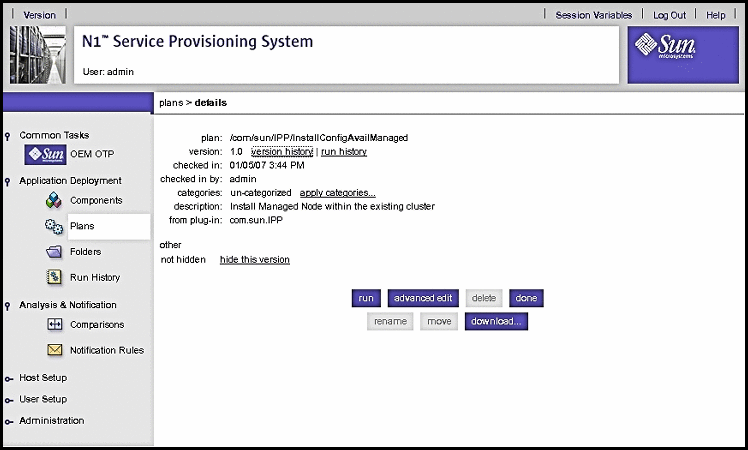
Click Step 2. OTP High Availability Framework on Additional Hosts: Install and Configure.
The edit availability plan page appears.
Figure 5–15 Clustered OTP Hosts Edit Availability Plan Page
-
Click run.
The Availability Plan Variables page appears. Scroll the page down to view the variables:
Figure 5–16 Clustered OTP Hosts Availability Plan Variables Page
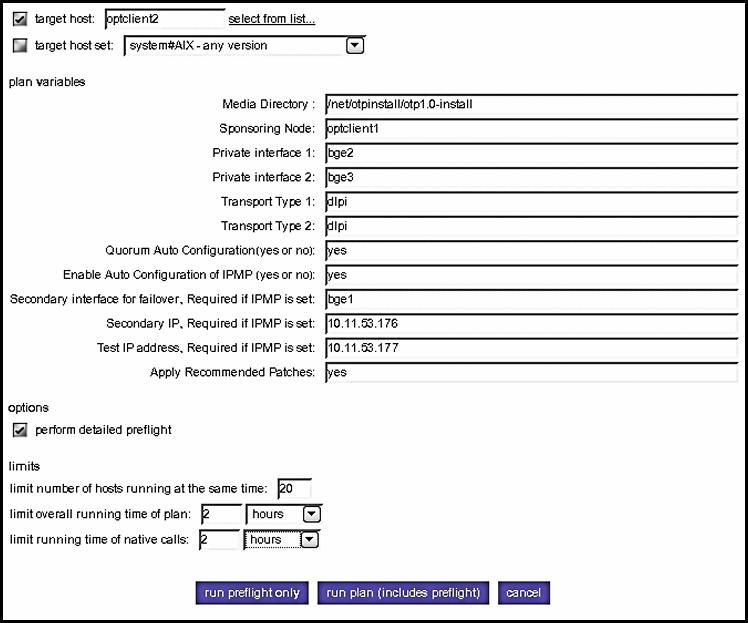
Type the information in the plan variables fields according to your Clustered OTP Host Plan Worksheet. Refer to the OTP System Plan Settings Descriptions for information about each variable.
 Caution –
 Set limit overall running time of plan and limit running time of native calls to 2 hours each.
-
Click run plan (includes preflight).
The page refreshes, and a progress bar is displayed during the provisioning process.
The provisioning process:
-
Installs required Solaris OS patches
-
Installs the OTP high availability framework
-
Configures the clustered OTP host
-
Reboots the clustered OTP host
-
Verifies the clustered OTP host configuration
-
-
If you chose no for Quorum Auto Configuration on a two-host cluster, you must manually select and configure the quorum disk as follows.
Note –The following sub-steps apply only to a two-host cluster. If you are setting up the OTP high availability framework on a three-host or more clustered OTP system, this step is optional.
-
Open a separate terminal window and log in as root to the first OTP host.
-
Type /usr/cluster/bin/scdidadm -L to display the cluster disk information. For example:
# /usr/cluster/bin/scdidadm -L
                1        otpclient1:/dev/rdsk/c0t8d0     /dev/did/rdsk/d1
                1        otpclient2:/dev/rdsk/c0t8d0     /dev/did/rdsk/d1
                2        otpclient1:/dev/rdsk/c0t9d0     /dev/did/rdsk/d2
                2        otpclient2:/dev/rdsk/c0t9d0     /dev/did/rdsk/d2
                3        otpclient1:/dev/rdsk/c1t0d0     /dev/did/rdsk/d3
                4        otpclient1:/dev/rdsk/c1t1d0     /dev/did/rdsk/d4
                5        otpclient2:/dev/rdsk/c1t0d0     /dev/did/rdsk/d5
                6        otpclient2:/dev/rdsk/c1t1d0     /dev/did/rdsk/d6
In the above example, disks d1 and d2 are shared by both hosts of the two-host cluster. The quorum disk must be a shared disk.
-
Configure a quorum disk.
Type /usr/cluster/bin/scconf -a -q globaldev=shared disk ID where shared disk ID is a shared disk ID. For example:
# /usr/cluster/bin/scconf -a -q globaldev=d1
-
Type /usr/cluster/bin/scconf -c -q reset to reset the two-host cluster to normal mode.
-
 To Create Shared Storage on the Clustered OTP System
Set the hard drive variables according to your cluster settings. Failure to do so will result in OTP high availability framework installation failure.
Before You Begin
The OTP high availability framework must be set up on all OTP hosts in the clustered OTP system.
-
Create the shared storage meta database on all clustered OTP hosts.
The following steps must be performed for each clustered OTP host.
-
Log in to the clustered OTP host as root (su - root).
-
Determine the drive on which root is mounted and the available free space.
Typeprtvtoc `mount | awk '/^\/ / { print $3 }'` to list the hard drive slices and available space.
For example:
# prtvtoc `mount | awk '/^\/ / { print $3 }'` * /dev/rdsk/c0t0d0s0 partition map * * Dimensions: * 512 bytes/sector * 424 sectors/track * 24 tracks/cylinder * 10176 sectors/cylinder * 14089 cylinders * 14087 accessible cylinders * * Flags: * 1: unmountable * 10: read-only * * Unallocated space: * First Sector Last * Sector Count Sector * 63620352 79728960 143349311 * * First Sector Last * Partition Tag Flags Sector Count Sector Mount Directory 0 2 00 8201856 51205632 59407487 / 1 3 01 0 8201856 8201855 2 5 00 0 143349312 143349311 3 0 00 59407488 2106432 61513919 /globaldevices 7 0 00 61513920 2106432 63620351 -
Create the database.
Type metadb -a -f -c 6 disk slice where disk slice is an available file system.
For example, based on the example in the previous step:
# metadb -a -f -c 6 c0t0d0s7
-
-
Create the shared storage files only on the first OTP host.
The first OTP host must be connected to the shared storage.
-
Log in to the first OTP host as root (su - root).
-
Type the scdidadm command to determine which disks are seen on all nodes of cluster and choose one to be the shared disk to metaset.
In the following example d4, d5, d6, and d7 are shared disks.
# /usr/cluster/bin/scdidadm -L
1   otpclient1:/dev/rdsk/c1t0d0    /dev/did/rdsk/d1
2   otpclient1:/dev/rdsk/c2t0d0    /dev/did/rdsk/d2
3   otpclient1:/dev/rdsk/c2t1d0    /dev/did/rdsk/d3
4   otpclient1:/dev/rdsk/c3t600C0FF000000000092C187A9755BE14d0 /dev/did/rdsk/d4
4   otpclient2:/dev/rdsk/c3t600C0FF000000000092C187A9755BE14d0 /dev/did/rdsk/d4
5   otpclient1:/dev/rdsk/c3t600C0FF000000000092C187A9755BE13d0 /dev/did/rdsk/d5
5   otpclient2:/dev/rdsk/c3t600C0FF000000000092C187A9755BE13d0 /dev/did/rdsk/d5
6   otpclient1:/dev/rdsk/c3t600C0FF000000000092C187A9755BE12d0 /dev/did/rdsk/d6
6   otpclient2:/dev/rdsk/c3t600C0FF000000000092C187A9755BE12d0 /dev/did/rdsk/d6
7   otpclient1:/dev/rdsk/c3t600C0FF000000000092C187A9755BE11d0 /dev/did/rdsk/d7
7   otpclient2:/dev/rdsk/c3t600C0FF000000000092C187A9755BE11d0 /dev/did/rdsk/d7
8   otpclient2:/dev/rdsk/c1t0d0    /dev/did/rdsk/d8
9   otpclient2:/dev/rdsk/c2t0d0    /dev/did/rdsk/d9
10  otpclient2:/dev/rdsk/c2t1d0    /dev/did/rdsk/d10
-
Add the additional OTP hosts.
Type metaset -s sps–dg -a -h otpclient1 otpclientn where otpclient1 otpclientn is the list of OTP hosts separated by a space. For example, assuming that otpclient1 is the First OTP host
# metaset -s sps–dg -a -h  otpclient2 otpclient3 otpclient4 otpclient5 \
ontclient6 otpclient7 otpclient8
-
Type metaset -s sps–dg -a shared-disk to add the shared disk to metaset.
In the following example, the d7 shared disk is added:
# metaset -s sps–dg -a /dev/did/rdsk/d7
-
Type metainit -s sps–dg d0 1 1 /dev/did/rdsk/d7s0
-
Type newfs /dev/md/sps–dg/rdsk/d0
-
On a two-host cluster only, set up the mediator strings for the sps-dg disk group.
Type metaset -s sps–dg -a -m otpclient1 otpclientn where otpclient1 otpclientn is the list of OTP hosts separated by a space. For example:
# metaset -s sps–dg -a -m otpclient1 otpclient2 otpclient3 otpclient4 otpclient5 \
ontclient6 otpclient7 otpclient8
-
Type metaset to verify the mediator host setup.
The following example shows hosts otpclient1 and otpclient2 set up as mediator hosts.
# metaset
Set name = sps–dg, Set number = 1
Host                Owner
  otpclient1         Yes
  otpclient2
Mediator Host(s)    Aliases
  otpclient1
  otpclient2
Driv Dbase
d4   Yes
-
-
Update the /etc/vfstab file on all clustered OTP hosts.
The following steps must be performed for each host.
Next Steps
Set up the system management and provisioning services on the first OTP host as described in the next procedure.
 To Set Up OTP System Management and Provisioning
Services on the First OTP Host
Before You Begin
Shared storage must be set up on the first OTP host as described in the previous procedure.
-
Open a Web browser and log in to the external OTP installation server service provisioning service.
Go to URL http://install server:9090 where install server is either the IP address or the fully qualified name of the external OTP installation server.
-
Click OEM OTP to display the Open Telecommunications Platform home page.
-
Click Step 3. OTP System Management and Provisioning Services on First Host: Install and Configure.
The edit System Management and Application Provisioning plan page appears.
-
Click run.
The System Management and Application Provisioning Plan Variables page appears. Scroll the page down to display the variables
Figure 5–17 Clustered OTP Host System Management and Application Provisioning Plan Variables Page: First OTP Host
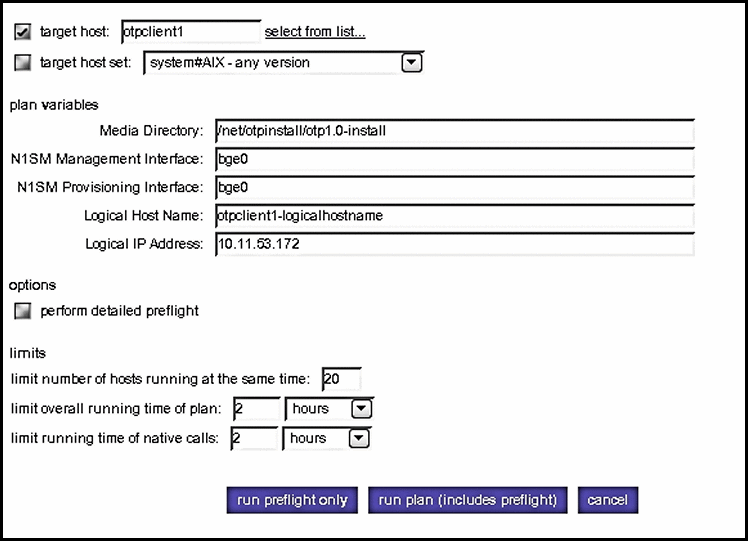
Type the information in the plan variables fields according to your Clustered OTP Host Plan Worksheet. Refer to the OTP System Plan Settings Descriptions for information about each variable.
 Caution –
 Set limit overall running time of plan and limit running time of native calls to 2 hours each.
-
Click run plan (includes preflight).
The page refreshes, and a progress bar is displayed during the provisioning process.
The provisioning process:
-
Installs the Web console
-
Applies patches required by the Open Telecommunications Platform
-
Installs the system management agent
-
Installs the system management service
-
Installs the service provisioning service
-
Installs Java patches
When the provisioning process completes, click done.
-
 To Set Up OTP System Management and Provisioning
Services on the Additional OTP Hosts
Before You Begin
System management and provisioning services must be set up on the first OTP host as described in the previous procedure.
-
Open a Web browser and log in to the external OTP installation server service provisioning service.
Go to URL http://install server:9090 where install server is either the IP address or the fully qualified name of the external OTP installation server.
-
Click OEM OTP to display the Open Telecommunications Platform home page.
-
Click Step 4. OTP System Management and Provisioning Service on Additional Hosts: Install and Configure.
The edit System Management and Application Provisioning plan page appears.
-
Click run.
The System Management and Application Provisioning Plan Variables page appears. Scroll the page down to display the variables
Figure 5–18 Clustered OTP Host System Management and Application Provisioning Plan Variables Page: Additional OTP Host
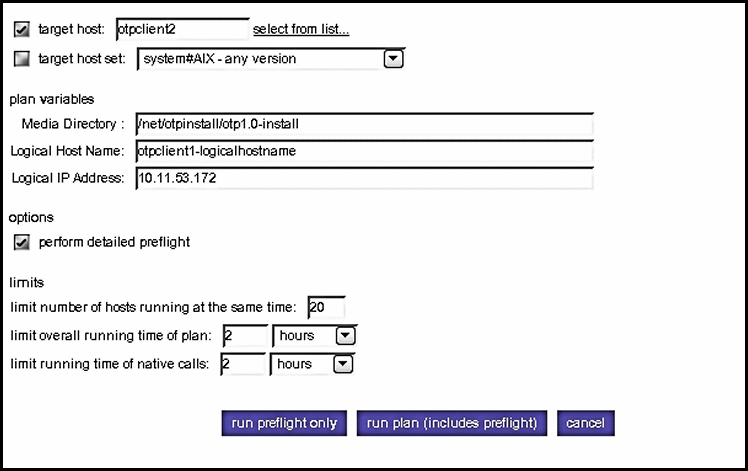
Type the information in the plan variables fields according to your Clustered OTP Host Plan Worksheet for this OTP host. Refer to the OTP System Plan Settings Descriptions for information about each variable.
 Caution –
 Set limit overall running time of plan and limit running time of native calls to 2 hours each.
-
Click run plan (includes preflight).
The page refreshes, and a progress bar is displayed during the provisioning process.
The provisioning process:
-
Installs the Web console
-
Applies patches required by the Open Telecommunications Platform
-
Installs the system management agent
-
Installs the system management service
-
Installs the service provisioning service
-
Installs Java patches
When the provisioning process completes, click done.
-
Next Steps
Repeat this procedure for the next OTP host in your clustered OTP system.
When you have finished setting up system management and provisioning services on all OTP hosts, enable high availability on the first OTP host as described in the next procedure.
 To Enable High Availability for the OTP Provisioning Service on
the First OTP Host
Before You Begin
System management and provisioning services must be set up on the additional OTP hosts as described in the previous procedure.
-
Open a Web browser and log in to the external OTP installation server service provisioning service.
Go to URL http://install server:9090 where install server is either the IP address or the fully-qualifed name of the external OTP installation server.
-
Click OEM OTP to display the Open Telecommunications Platform home page.
-
Click Step 5. OTP High Availability for Provisioning Service on First Host: Enable beneath Multi Cluster Setup in the central menu.
The edit High Availability plan page appears.
-
Click run.
The High Availability Plan Variables page appears. Scroll the page down to display the variables
Figure 5–19 Clustered OTP Host High Availability Plan Variables Page: First OTP Host
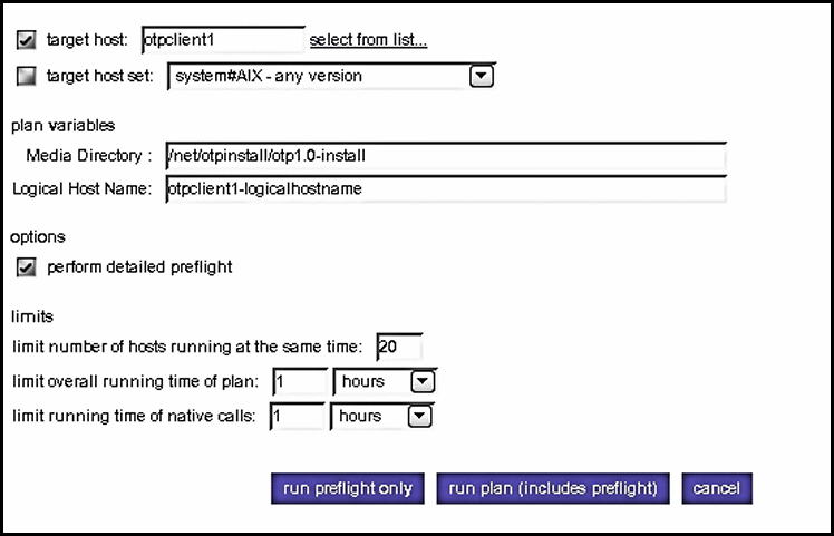
Type the information in the plan variables fields according to your Clustered OTP Host Plan Worksheet. Refer to the OTP System Plan Settings Descriptions for information about each variable.
 Caution –
 Set limit overall running time of plan and limit running time of native calls to 2 hours each.
-
Click run plan (includes preflight).
The page refreshes, and a progress bar is displayed during the provisioning process.
The provisioning process installs and enables the application provisioning service high availability agent.
When the provisioning process completes, click done.
-
Log in as root on thefirst OTP host and restart the remote agent.
Type /etc/init.d/n1spsagent restart to restart the remote agent. If the remote agent is not restarted, then the service provisioning service on the first OTP host will not work properly.
-
Configure and enable fail-over.
-
Type /usr/cluster/bin/scswitch -F -g otp-system-rg to take the remote group offline.
-
Type the following commands in the sequence shown to disable cluster resources.
/usr/cluster/bin/scswitch -n -j otp-spsms-rs
/usr/cluster/bin/scswitch -n -j otp-spsra-rs
/usr/cluster/bin/scswitch -n -j otp-sps-hastorage-plus
/usr/cluster/bin/scswitch -n -j otp-lhn
-
Type /usr/cluster/bin/scswitch -u -g otp-system-rg to put the remote group into the unmanaged state.
-
Type /usr/cluster/bin/scrgadm -c -j otp-spsra-rs -x Stop_signal="15" to change the Stop_signal property of the remote agent resource to 15.
-
Type /usr/cluster/bin/scrgadm -c -j otp-spsms-rs -x Stop_signal="15" to change the Stop_signal property of the management service resource to 15.
-
Type /usr/cluster/bin/scswitch -o -g otp-system-rg to put the remote group into the managed state.
-
Type /usr/cluster/bin/scswitch -Z -g otp-system-rg to bring the remote group back online.
This completes the Open Telecommunications Platform graphical user interface installation process for a clustered OTP system.
-
- © 2010, Oracle Corporation and/or its affiliates
