| Skip Navigation Links | |
| Exit Print View | |

|
Sun Server X3-2 HTML Documentation Collection |
Getting the Latest Software and Firmware
Preparing the Site for Installation
About the Installation Procedure
Installation Procedure Overview
About Server Features and Components
Front Panel Status Indicators, Connectors, and Drives
Back Panel Status Indicators, Connectors, and PCIe Slots
Server Management Software Overview
Preparing for Server Installation
Tools and Equipment Needed for Installation
Optional Component Installation
Installing the Server Into a Rack
Safety Precautions When Rackmounting the Server
Stabilize the Rack for Installation
Attach Tool-less Slide-Rail Assemblies
Install the Server Into the Slide-Rail Assemblies
Install the Second-Generation Cable Management Arm
Remove the Second-Generation Cable Management Arm
Install the First-Generation Cable Management Arm
Rear Cable Connections and Ports
Attaching Data Cables and Power Cords to the Server
Oracle ILOM Hardware and Interfaces
Logging In to Oracle ILOM Using a Local Serial Connection
Logging In to Oracle ILOM Using a Remote Ethernet Connection
Accessing the Host Console Through Oracle ILOM
Troubleshooting the Service Processor Connection
Setting Up Software and Firmware Using Oracle System Assistant
Setting Up an Operating System and Drivers
Configuring Server Drives for OS Installation
RAID Configuration Requirements
Configuring Storage Drives Into RAID Volumes Using Oracle System Assistant
Configuring RAID Using the BIOS RAID Configuration Utilities
Configuring the Preinstalled Oracle Solaris 11 Operating System
Preinstalled Operating System RAID Limitations
Oracle Solaris Configuration Worksheet
Configure the Preinstalled Oracle Solaris 11 Operating System
Oracle Solaris 11 Operating System Documentation
Configuring the Preinstalled Oracle Linux 6.x Operating System
Oracle Linux 6.x Configuration Worksheet
Configure the Preinstalled Oracle Linux 6 Operating System
Register and Update Your Linux Operating System
Oracle Linux Operating System Documentation
Configuring the Preinstalled Oracle VM 3.x Software
Preinstalled Oracle VM Server and Oracle VM Manager Compatibility Requirements
Oracle VM Server Configuration Worksheet
Configure the Preinstalled Oracle VM
Controlling System Power and Troubleshooting Installation Issues
Power Off the Server for Orderly Shutdown
Power Off the Server for Immediate Shutdown
Technical Support Information Worksheet
Locating the System Serial Number
Getting Server Firmware and Software
Firmware and Software Access Options
Getting Firmware and Software from MOS or PMR
Installing Updates Using Other Methods
About Oracle Solaris Operating System Installs
Oracle Solaris OS Installation Task Map
Selecting the Console Display Option
Selecting the Boot Media Option
Selecting the Installation Target Option
Oracle Solaris OS Installation Options
Preparing to Install the Operating System
Installing the Oracle Solaris Operating System
Installing Oracle Solaris 10 or 11 Operating System on a Single System Using Media
Getting Server Firmware and Software
Firmware and Software Access Options
Getting Firmware and Software From MOS or PMR
Installing Updates Using Other Methods
Oracle VM Installation Task Map
Selecting the Console Display Option
Selecting the Boot Media Option
Selecting the Installation Target Option
Oracle VM Installation Options
Single-Server Installation Methods
Assisted Oracle VM Installation
Oracle System Assistant Overview
Oracle System Assistant Install OS Task
Obtaining Oracle System Assistant
Preparing to Install Oracle VM
Verify the BIOS Factory Defaults
Installing Oracle VM on a Single System Using Oracle System Assistant
Installing Oracle VM on a Single System Using Media
Post Installation Tasks for Oracle VM
Configuring Network Interfaces
Getting Server Firmware and Software
Firmware and Software Access Options
Getting Firmware and Software From MOS or PMR
Installing Updates Using Other Methods
About Linux Operating System Installs
Supported Linux Operating Systems
Oracle Unbreakable Enterprise Kernel for Linux
Selecting the Console Display Option
Selecting the Boot Media Option
Selecting the Installation Target Option
Oracle System Assistant Overview
Preparing to Install the Operating System
Configuring the SLES 11 SP1 Operating System Software to Support Network Connections
Installing the Linux Operating System
Installing a Linux OS on a Single System Using Oracle System Assistant
Installing Oracle Linux on a Single System Using Media
Installing Red Hat Enterprise Linux on a Single System Using Media
Installing SUSE Linux Enterprise Server on a Single System Using Media
Configuring Network Interfaces
Getting Server Firmware and Software
Firmware and Software Access Options
Getting Firmware and Software From MOS or PMR
Installing Updates Using Other Methods
About Microsoft Windows Server Operating System Installs
Windows OS Installation Task Map
Supported Windows Operating Systems
SAS PCIe HBAs Requiring LSI Mass Storage Driver for Windows Server 2008 SP2
Selecting the Console Display Option
Selecting the Boot Media Option
Selecting the Installation Target Option
Windows OS Installation Options
Oracle System Assistant Overview
Preparing to Install the Operating System
Installing Windows Server Operating System
Installing Windows Server on a Single System Using Oracle System Assistant
Installing Windows Server on a Single System Using Media
Post Installation Tasks for Windows Server
Supplemental Software Component Options
Installing Device Drivers and Supplemental Software
Getting Server Firmware and Software
Firmware and Software Access Options
Getting Firmware and Software from MOS or PMR
Installing Updates Using Other Methods
VMware ESXi Installation Task Map
Supported VMware ESXi Software
Selecting the Console Display Option
Selecting the Boot Media Option
Selecting the Installation Target Option
VMware ESXi Installation Options
Preparing to Install VMware ESXi
Configuring the VMware ESXi 5.0 Software or the Server Hardware to Support Network Connections
Installing VMware ESXi on a Single System Using Media
Post Installation Tasks for VMware ESXi
Configure Network Adapter Settings
Determine the MAC Address of a Connected Server Network Port
Update the VMware ESXi Software
Configuring Network Interfaces
Getting Server Firmware and Software
Firmware and Software Access Options
Getting Firmware and Software from MOS or PMR
Installing Updates Using Other Methods
About Server and Component Status Indicators
Service Troubleshooting Task List
Locate the Server Serial Number
Electrostatic Discharge Safety
Preparing the Server for Component Replacement
Servicing CRUs That Do Not Require Server Power Off
Servicing Storage Drives (CRU)
Servicing Power Supplies (CRU)
Servicing CRUs That Require Server Power Off
Servicing the Internal USB Flash Drives (CRU)
Selecting the Correct Processor Removal/Replacement Tool
Servicing the Disk Backplane (FRU)
Servicing the Front Indicator Module (FRU)
Remove the Front Indicator Module From a Server With 2.5-Inch Storage Drives
Install the Front Indicator Module Into a Server With 2.5-Inch Storage Drives
Remove the Front Indicator Module From a Server With 3.5-Inch Storage Drives
Install the Front Indicator Module Into a Server With 3.5-Inch Storage Drives
Servicing the Motherboard (FRU)
Servicing the SAS Cables (FRUs)
Remove Storage Drive SAS Cables
Install Storage Drive SAS Cables
Returning the Server to Operation
Removing and Installing Server Filler Panels
Reinstall the Server Chassis Into the Rack
Return the Server to the Normal Rack Position
Reconnect Data Cables and Power Cords
Getting Server Firmware and Software
Firmware and Software Access Options
Getting Firmware and Software From MOS or PMR
Installing Updates Using Other Methods
Planning the System Management Environment
Choosing Tools for Single System Management
Choosing Tools for Multiple System Management
System Management Tools Overview
Common System Management Tasks
Common System Administrative Tasks
Evaluating the Server Environment
Installing System Management Tools
System Management Documentation
Accessing System Management Tools
Accessing Oracle System Assistant
Accessing Oracle Hardware Management Pack
Setting Up Software and Firmware
Set Up Software and Firmware Using Oracle System Assistant
Set Up Software and Firmware Using Oracle ILOM
Set Up Software and Firmware Using Oracle Hardware Management Pack
Setting Up the Server Using Oracle System Assistant
Organization of Oracle System Assistant
Configure the Server Using Oracle System Assistant
Mounting the Oracle System Assistant USB Flash Drive
Troubleshooting Oracle System Assistant
Accessing the Oracle System Assistant Filesystem
Managing the Server Using Oracle ILOM
Oracle ILOM Features for Oracle x86 Servers
Supported HBA Disk Controllers
Creating a RAID Volume Before Installing an Operating System
Creating a RAID Volume After Installing an Operating System
Using Oracle ILOM to Monitor Storage Devices
Setting Up BIOS Configuration Parameters
Managing the BIOS Configuration
Accessing the BIOS Setup Utility
Using BIOS for Resource Allocation
Common BIOS Setup Utility Tasks
BIOS Setup Utility Menu Options
UEFI Driver Control Menu Selections
BIOS Save & Exit Menu Selections
Monitoring Components and Identifying SNMP Messages
Monitoring Component Health and Faults Using Oracle ILOM
Identifying SNMP Trap Messages
Getting Server Firmware and Software
Firmware and Software Access Options
Getting Firmware and Software from MOS or PMR
 | Caution - Processor(s) should be removed only by an Oracle qualified service technician. |
 | Caution - The processor socket used in the Sun Server X3-2 is the Intel LGA2011. Processor removal and replacement must be done using the green color-coded tool (see Removing a Processor). Using a tool with a different color code might result in damage to the processor and the socket. The supported replacement processor for the server includes the correct tool. |
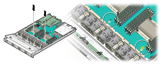
Note - When the Fault Remind button is pressed, a LED located next to the Fault Remind button lights green to indicate that there is sufficient voltage present in the fault remind circuit to light any fault LEDs that were set due to a failure. If this LED fails to light when you press the Fault Remind button, it is likely that the capacitor powering the fault remind circuit has lost its charge. This can happen if the Fault Remind button is pressed for a long time with fault LEDs lit or if power has been removed from the server for more than 15 minutes.
The processor fault LEDs are located next to the processor(s).
If processor fault LED is off: processor is operating properly.
If processor fault LED is on (amber): processor is faulty and should be replaced.
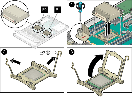
Note - Processor 0 (P0) is on the left side when viewing the server from the front.

Turn the screws counterclockwise alternately one and one half turns until they are fully removed.

A thin layer of thermal grease separates the heat sink and the processor. This grease also acts as an adhesive.
Note - Do not allow the thermal grease to contaminate the work space or other components.
Be very careful not to get the thermal grease on your fingers.
 | Caution - Failure to clean the heatsink prior to removing the processor could result in the accidental contamination of the processor socket or other components. Also, be careful not to get the grease on your fingers as this could result in contamination of components. |
 | Caution - Whenever you remove a processor, you should replace it with another processor and reinstall the processor heatsink; otherwise, the server might overheat due to improper airflow. For instructions for installing a processor, see Install a Processor. |
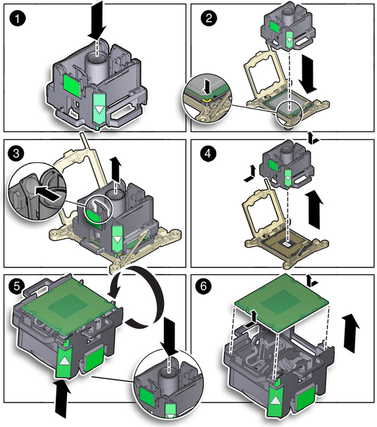
To properly position the tool over the processor socket, rotate the tool until the green triangle on the side of the tool is facing the front of the server and it is over the left side of the processor socket when viewing the server from the front.
An audible click indicates that the processor is engaged.
Figure 64 Removing a Processor
