| Skip Navigation Links | |
| Exit Print View | |

|
Oracle ZFS Storage ZS3-ES Service Manual |
About the Oracle ZFS Storage ZS3-ES
Front Panel Controls and Indicators
About Server and Component Status Indicators
Server General Status Indicators
Storage Drive Status Indicators
Power Supply Status Indicators
Service Troubleshooting Task List
Locate the Server Serial Number
Inspect Internal Server Components
Electrostatic Discharge Safety
Preparing the Server for Component Replacement
Disconnect Cables From the Server
Extend the Server to the Maintenance Position
Remove the Server From the Rack
Servicing CRUs That Do Not Require Server Power Off
Servicing Storage Drives (CRU)
Storage Drives Hot-Plug Conditions
Storage Drive Status Indicators
Servicing Power Supplies (CRU)
Power Supply Status Indicators
Servicing CRUs That Require Server Power Off
DIMM and Processor Physical Layout
Inconsistencies Between DIMM Fault LEDs and the BIOS Isolation of Faulty DIMMs
Identify and Remove Faulty DIMMs
PCIe Riser Location and Differences
Remove a PCIe Riser From PCIe Slot 1 or 2
Install a PCIe Riser Into PCIe Slot 1 or 2
Remove a PCIe Riser From PCIe Slots 3 and 4
Install a PCIe Riser Into PCIe Slots 3 and 4
Identify a Faulty PCIe Card in the BUI
Remove a PCIe Card From PCIe Slot 1 or 2
Install a PCIe Card in PCIe Slot 1 or 2
Remove a PCIe Card From PCIe Slot 3
Install a PCIe Card in the PCIe Riser in Slot 3
Install the Internal HBA Card in the PCIe Riser
Servicing the Internal USB Flash Drive (CRU)
Remove an Internal USB Flash Drive
Install an Internal USB Flash Drive
Servicing the Disk Backplane (FRU)
Servicing the Front Indicator Module (FRU)
Remove the Front Indicator Module
Install the Front Indicator Module
Servicing the Motherboard (FRU)
Servicing the SAS Cables (FRUs)
Remove Storage Drive SAS Cables
Install Storage Drive SAS Cables
Returning the Server to Operation
Removing and Installing Server Filler Panels
Remove and Install Filler Panels
Reinstall the Server Chassis Into the Rack
Return the Server to the Normal Rack Position
Install the Cable Management Arm
Reconnect Data Cables and Power Cords
Getting Server Firmware and Software
Firmware and Software Access Options
Before You Begin
You do not have to power off the server to service the fan modules.
You should not begin this procedure unless you have a replacement fan and you are ready to install it right away.
Go to Maintenance > Hardware, click the Show Details link for the server, click the Fan submenu, and look for the fan module with an amber icon to the left of its ID. Click on the row with the failed fan module to physically locate it in the server image.
Note - Close the server fan door within 60 seconds to maintain adequate airflow to properly cool the server. Leaving the door open for more than 60 seconds, while the server is running, might cause the server to overheat and shut down.
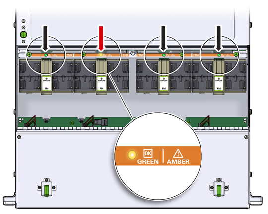
Each fan module has a status indicator (LED). If the LED is lit amber, the fan has failed. The status LEDs are located on the chassis mid-wall adjacent to and aligned with the fan module, as shown in the following figure.
Figure 15 Fan Module LEDs

|
 | Caution - When removing a fan module, do not rock it back and forth. Rocking the fans module can cause damage to the motherboard connectors. |
 | Caution - When changing the fan modules, note that only the fan modules can be removed or replaced. Do not service any other components in the fan compartment unless the system is shut down and the power cords are removed. |
If you removed the fan assembly as part of another procedure, return to that procedure.
Otherwise, continue to Install a Fan Module.