| Skip Navigation Links | |
| Exit Print View | |

|
Oracle ZFS Storage ZS3-ES Service Manual |
About the Oracle ZFS Storage ZS3-ES
Front Panel Controls and Indicators
About Server and Component Status Indicators
Server General Status Indicators
Storage Drive Status Indicators
Power Supply Status Indicators
Service Troubleshooting Task List
Locate the Server Serial Number
Inspect Internal Server Components
Electrostatic Discharge Safety
Preparing the Server for Component Replacement
Emergency Server Power Down Using the Power Button
Emergency Server Power Down Using the Oracle ILOM CLI
Emergency Server Power Down Using the Oracle ILOM Web Interface
Disconnect Cables From the Server
Remove the Server From the Rack
Servicing CRUs That Do Not Require Server Power Off
Servicing Storage Drives (CRU)
Storage Drives Hot-Plug Conditions
Storage Drive Status Indicators
Servicing Power Supplies (CRU)
Power Supply Status Indicators
Servicing CRUs That Require Server Power Off
DIMM and Processor Physical Layout
Inconsistencies Between DIMM Fault LEDs and the BIOS Isolation of Faulty DIMMs
Identify and Remove Faulty DIMMs
PCIe Riser Location and Differences
Remove a PCIe Riser From PCIe Slot 1 or 2
Install a PCIe Riser Into PCIe Slot 1 or 2
Remove a PCIe Riser From PCIe Slots 3 and 4
Install a PCIe Riser Into PCIe Slots 3 and 4
Identify a Faulty PCIe Card in the BUI
Remove a PCIe Card From PCIe Slot 1 or 2
Install a PCIe Card in PCIe Slot 1 or 2
Remove a PCIe Card From PCIe Slot 3
Install a PCIe Card in the PCIe Riser in Slot 3
Install the Internal HBA Card in the PCIe Riser
Servicing the Internal USB Flash Drive (CRU)
Remove an Internal USB Flash Drive
Install an Internal USB Flash Drive
Servicing the Disk Backplane (FRU)
Servicing the Front Indicator Module (FRU)
Remove the Front Indicator Module
Install the Front Indicator Module
Servicing the Motherboard (FRU)
Servicing the SAS Cables (FRUs)
Remove Storage Drive SAS Cables
Install Storage Drive SAS Cables
Returning the Server to Operation
Removing and Installing Server Filler Panels
Remove and Install Filler Panels
Reinstall the Server Chassis Into the Rack
Return the Server to the Normal Rack Position
Install the Cable Management Arm
Reconnect Data Cables and Power Cords
Getting Server Firmware and Software
Firmware and Software Access Options
Before You Begin
The following components can be serviced with the server in the maintenance position:
Storage drives
Fan modules
Power supplies
PCIe risers
PCIe cards
DDR3 DIMMs
Internal USB flash drive
Motherboard Battery
Processors
Disk backplane
FIM (front indicator module)
Motherboard
If the server is installed in a rack with extendable slide-rails, use this procedure to extend the server to the maintenance position.
Refer to your rack documentation for detailed instructions.
 | Caution - To reduce the risk of personal injury, stabilize the expansion rack cabinet and extend all anti-tilt devices before extending the server from the rack. |
Open and remove the front and rear doors from the rack cabinet.
The front and rear doors need to be removed only if they impinge on the mounting bay.
To prevent the rack cabinet from tipping during the installation, fully extend the rack cabinet's anti-tilt legs or anti-tilt bar, which are located at the bottom front of the rack cabinet.
If there are leveling feet beneath the rack cabinet to prevent it from rolling, extend these leveling feet fully downward to the floor.
Although the cable management arm (CMA) that is supplied with the server is hinged to accommodate extending the server, you should ensure that all cables and cords are capable of extending.
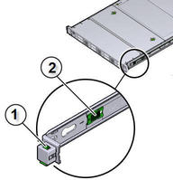
Note - The slide-rail locks are located behind the flip-down handles on the front of the server. The slide-rail locks are released when the flip-down handles are pulled down.
The server is now in the extended maintenance position.
Figure 4 Slide-Rail Release Latches

Figure Legend
1 Slide-rail lock
2 Slide-rail release tab