| Skip Navigation Links | |
| Exit Print View | |

|
Oracle® ZFS Storage Appliance Administration Guide |
Chapter 1 Oracle ZFS Storage Appliance Overview
Chapter 3 Initial Configuration
Chapter 4 Network Configuration
Chapter 5 Storage Configuration
Chapter 6 Storage Area Network Configuration
Chapter 8 Setting ZFSSA Preferences
Chapter 10 Cluster Configuration
Understanding Cluster Resource Management
Configuration Changes in a Clustered Environment
Clustering Considerations for Storage
Clustering Considerations for Networking
Clustering Considerations for Infiniband
Clustering Redundant Path Scenarios
Preventing 'Split-Brain' Conditions
Estimating and Reducing Takeover Impact
Cluster Configuration Using the BUI
Configuring Clustering Using the CLI
Shutting Down a Clustered Configuration
Cluster Configuration BUI Page
Chapter 12 Shares, Projects, and Schema
Clustered head nodes must be connected together using the cluster interconnect ports located at the back of the controller.
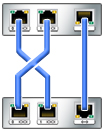
Figure 10-11 ZS3-2 Cluster Cabling

The ZS3-2 controller provides three redundant links that enable the heads to communicate: two serial links (the first two connectors) and an Ethernet link (the third connector).
Using straight-through Cat 5-or-better Ethernet cables, (three 1m cables ship with your cluster configuration), connect the head node according to the diagram at left.
The cluster cabling can be performed either prior to powering on either head node, or can be performed live while executing the cluster setup guided task. The user interface will show the status of each link, as shown later in this page. You must have established all three links before cluster configuration will proceed.
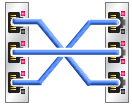
Figure 10-12 ZS3-4 and 7x20 Cluster Cabling

The ZS3-4 and 7x20 controllers provide three redundant links that enable the heads to communicate: two serial links (the outer two connectors) and an Ethernet link (the middle connector).
Using straight-through Cat 5-or-better Ethernet cables, (three 1m cables ship with your cluster configuration), connect the head node according to the diagram at left.
The cluster cabling can be performed either prior to powering on either head node, or can be performed live while executing the cluster setup guided task. The user interface will show the status of each link, as shown later in this page. You must have established all three links before cluster configuration will proceed.