Go to main content

Guide d'installation des serveurs Oracle® SuperCluster série M7

Quitter la vue de l'impression

Mis à jour : Février 2016


Référence de câblage entre commutateurs IB

Les commutateurs IB sont câblés ensemble à l'usine comme indiqué dans cette illustration et ce tableau.


Remarque - Pour plus d'informations sur les commutateurs IB, reportez-vous au document Sun Datacenter InfiniBand Switch 36 HTML Collection for Firmware Version 2.1 à l'adresse http://docs.oracle.com/cd/E36265_01.

Remarque -  Pour plus d'informations sur l'interconnexion de plusieurs racks, reportez-vous à Connexion de plusieurs systèmes SuperCluster M7 et Connexion de racks d'extension.
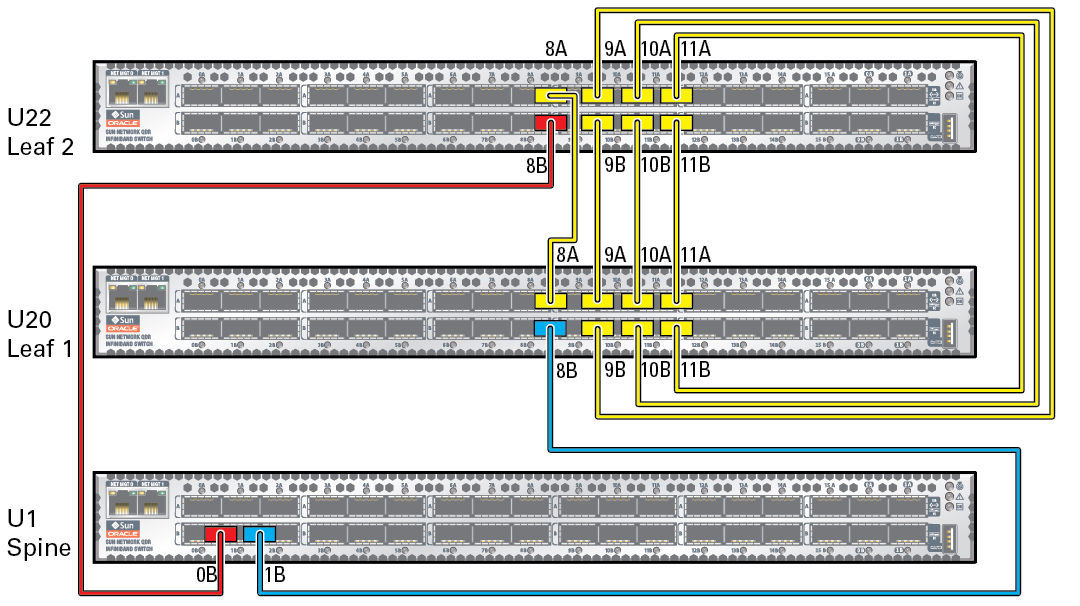
image:Figure illustrant les connexions de câble des commutateurs IB.
X = installé à l'usine
Depuis
Composant
Depuis
l'emplacement
Depuis
Port
A
Composant
A
l'emplacement
A
Port
X
Commutateur Spine
U1
0B
Commutateur Leaf 2
U24
8B
X
Commutateur Spine
U1
1B
Commutateur Leaf 1
U24
8B
X
Commutateur Leaf 1
U18
8A
Commutateur Leaf 2
U24
8A
X
Commutateur Leaf 1
U18
9A
Commutateur Leaf 2
U24
9B
X
Commutateur Leaf 1
U18
9B
Commutateur Leaf 2
U24
9A
X
Commutateur Leaf 1
U18
10A
Commutateur Leaf 2
U24
10B
X
Commutateur Leaf 1
U18
10B
Commutateur Leaf 2
U24
10A
X
Commutateur Leaf 1
U18
11A
Commutateur Leaf 2
U24
11B
X
Commutateur Leaf 1
U18
11B
Commutateur Leaf 2
U24
11A

Informations connexes