Overview of ZS5-4 Controller
This section provides an overview of the Oracle ZFS Storage ZS5-4 controller. For installation instructions, refer to Installing a ZS5-4 Controller. For service instructions, refer to Servicing the ZS5-4 Controller in Oracle ZFS Storage Appliance Customer Service Manual.
Refer to http://oracle.com/zfsstorage for the most recent component specification.
ZS5-4 Physical Specifications
The ZS5-4 controller chassis dimensions are as follows:
|
ZS5-4 Electrical Specifications
The ZS5-4 controller has two hot-swappable rear accessible power supplies with N+N redundancy. To understand the overall power consumption, see Oracle's online power calculator at http://www.oracle.com/goto/powercalculators.
|
ZS5-4 Acoustic Noise Emissions
In compliance with the requirements defined in ISO 9296, the workplace-dependent noise level of this product is less than 75 dBA (bystander position, max. ambient).
ZS5-4 Configuration Options
The ZS5-4 incorporates one or two controllers and one to forty-eight disk shelves. Each controller has eleven PCle Gen3 slots. Each controller includes six 2.5'' disk slots that accommodate two system disks. Read cache devices are installed in disk shelves; therefore, the remaining four disk slots have permanent filler panels. The following table describes the configuration options.
|
The most recent component specification is located at https://www.oracle.com/storage/nas/index.html.
ZS5-4 Front Panel Components
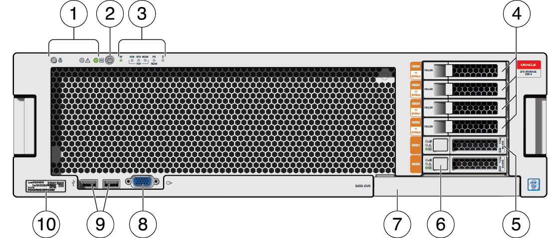
The ZS5-4 controller drive slots and front panel components are shown in the following figure.
Figure 22 ZS5-4 Front Panel

|
ZS5-4 Rear Panel Components
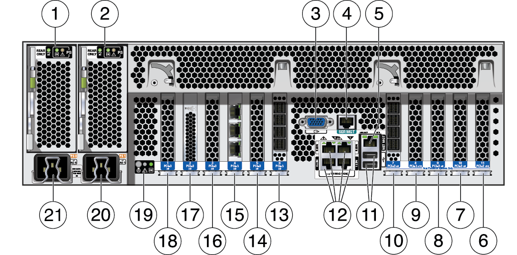
The ZS5-4 controller PCIe slots and rear panel components are shown in the following figure.
Figure 23 ZS5-4 Rear Panel

|
Cluster Interface Card Compatibility - The ZS5-4 controller contains a Version 3 cluster interface card, which is incompatible with Version 2.
For information about how to connect cables to form a cluster, see Connecting Cluster Cables in Oracle ZFS Storage Appliance Cabling Guide.