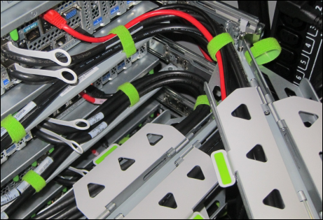
Adding Storage Servers to a Rack
The following sections describe how add storage servers to a Recovery Appliance rack:
Note:
-
Apply any patches to the switches and servers in the rack before extending the hardware.
-
You can extend the hardware while Recovery Appliance is online, and with no downtime. However, take extreme care.
Checking the Recovery Appliance Rack
Examine the Recovery Appliance physical systems for any problems:
-
Check the rack for damage.
-
Check the rack for loose or missing screws.
-
Check Recovery Appliance for the ordered hardware configuration.
-
Check that all cable connections are secure and well seated.
-
Check the power cables.
-
Ensure that the correct connectors were supplied for the data center facility power source.
-
Check the network data cables.
-
Check the site location tile arrangement for cable access and airflow.
-
Check the data center airflow into the front of Recovery Appliance.
Unpacking and Labeling the New Storage Servers
The Recovery Appliance racks are supplied with the InfiniBand and Cat5e harness connections for the maximum number of storage servers.
To prepare the new servers for installation:
Figure 7-1 shows the components of the server expansion kit.
Figure 7-1 Server Expansion Kit Components
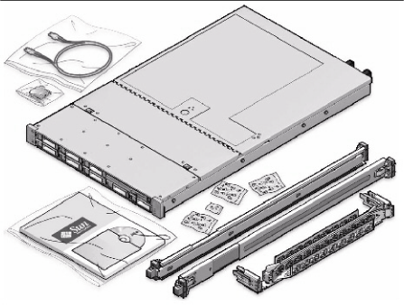
Description of "Figure 7-1 Server Expansion Kit Components"
Note:
All new equipment receives a Customer Support Identifier (CSI), including the new equipment for Recovery Appliance. Contact Oracle Support Services to reconcile the new CSI with the existing CSI for the Recovery Appliance rack. You must have the original instance or serial numbers and the new numbers when contacting Oracle Support Services.
Recovery Appliance RA23, RA21, X8M, and X8 through X5 Population Rules
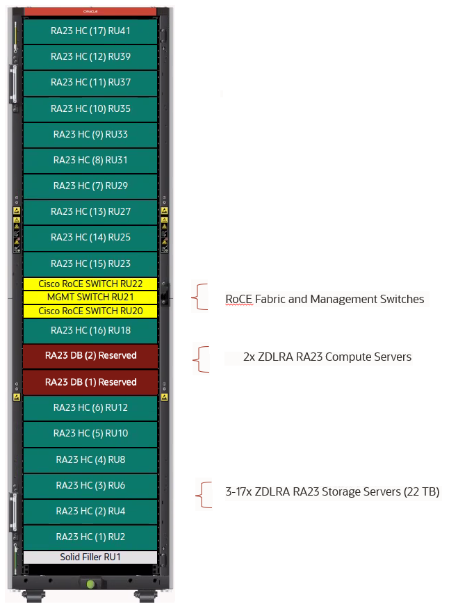
When adding storage servers to a Recovery Appliance RA23 follow the population rules listed in Table 7-1 and depicted in Figure 7-2. This assumes that the three storage servers of the base rack, minimum configuration are already in place at RU02 through RU06.
Table 7-1 Recovery Appliance RA23 Rack Population Rules
| Install Order | Rack Units | Rule |
|---|---|---|
|
1 |
RU08 to RU12 |
Install storage servers 4 through 6 from first available rack slot above existing storage servers at bottom and populate upward. |
|
2 |
RU29 to RU39 |
Install storage servers 7 through 12 starting at RU29 and populate upward until RU39. |
|
3 |
RU27 to RU23 |
Install storage servers 13 through 15 starting at RU27 and populate downward until RU23. |
|
4 |
RU18 |
Install storage server 16 at RU18 between existing storage server and lower RoCE network switch. |
|
5 |
RU41 |
Install storage server 17 at RU41, last slot at top of rack |
Figure 7-2 RA23 Rack Layout and Population Rules
When adding servers to a Recovery Appliance RA21, X8M, or X8 through X5 rack, follow the population rules listed in Table 7-2. This assumes that the three storage servers of the base rack are already in place.
Table 7-2 Recovery Appliance RA21, X8M, and X8 through X5 Rack Population Rules
| Install Order | Rack Units | Rule |
|---|---|---|
|
1 |
U08 to U15 |
Populate toward the top of the rack (4 units) |
|
2 |
U27 to U40 |
Populate toward the top of the rack (7 units) |
|
3 |
U26 to U23 |
Populate toward the bottom of the rack (2 units) |
|
4 |
U19 to U18 |
(1 unit) |
|
5 |
U41 to U42 |
(1 unit) |
Removing the Doors
To remove the doors on the Recovery Appliance rack:
-
Remove the front and rear doors, as follows:
-
Unlock the front and rear doors. The keys are in the shipping kit.
-
Open the doors.
-
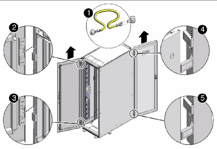
Detach the grounding straps connected to the doors by pressing down on the tabs of its quick-release connectors, and pull the straps from the frame.
-
Lift the doors up and off their hinges.
Description of the callouts in Figure 7-3:
1: Detaching the grounding cable
2: Top rear hinge
3: Bottom rear hinge
4: Top front hinge
5: Bottom front hinge
-
-
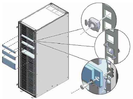
To remove the filler panels where the servers will be installed, use a No. 2 screwdriver to remove the M6 screws. The number of screws depends on the type of filler panel. Save the screws for future use.
Note:
If you are replacing the filler panels, then do not remove the Duosert cage nuts from the Radio Electronics Television Manufacturers Association (RETMA) rail holes.
Adding New Servers
You can extend Recovery Appliance X7, X6, or X5 to a maximum of 18 storage servers and Recovery Appliance X4 to a maximum of 14 storage servers. You can add any number of storage servers at a time, from one to 15 servers when starting with a minimum configuration.
To prepare for the installation:
-
Identify the rack unit where you will install the server. Fill the first available unit, starting from the bottom of the rack.
See "Recovery Appliance X8, X7, X6, and X5 Rack Layout" or "Recovery Appliance X4 Rack Layout", as applicable.
-
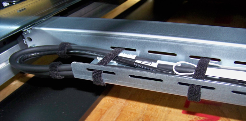
Remove and discard the trough, which attaches the cable harness when no server is installed in the unit.
-
Remove and discard the solid filler.
To install the rail assembly:
-
Position a mounting bracket against the chassis so that the slide-rail lock is at the server front, and the five keyhole openings on the mounting bracket are aligned with the five locating pins on the side of the chassis.
-
Orient the slide-rail assembly so that the ball-bearing track is forward and locked in place.
-
Starting on either side of the rack, align the rear of the slide-rail assembly against the inside of the rear rack rail, and push until the assembly locks into place with an audible click.
Figure 7-6 Aligning the Side-Rail Assembly With the Rack
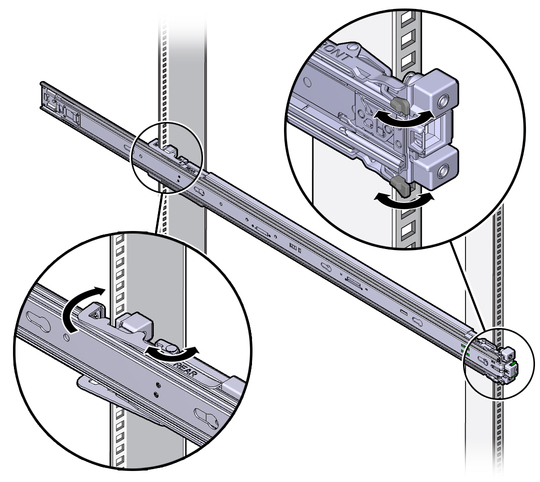
Description of "Figure 7-6 Aligning the Side-Rail Assembly With the Rack" -
Align the front of the slide-rail assembly against the outside of the front rack rail, and push until the assembly locks into place and you hear the click.
WARNING:
-
Installing a server requires a minimum of two people or a lift because of the weight of each server. Attempting this procedure alone can result in equipment damage, personal injury, or both.
-
Extend the rack anti-tip bar to prevent the rack from tipping during equipment installation.
-
For Recovery Appliance X4 racks, load the servers from the bottom up, so that the rack does not become top-heavy and tip over. See "Recovery Appliance X4 Rack Layout" for the designated location of each server.
-
For Recovery Appliance X6 or X5 racks, load the servers following the population rules. See "Recovery Appliance RA23, RA21, X8M, and X8 through X5 Population Rules".
To install the server:
-
Read the service label on the top cover of the server before installing a server into the rack.
-
Push the server into the slide rail assembly:
-
Push the slide rails into the slide rail assemblies as far as possible.
-
Position the server so the rear ends of the mounting brackets are aligned with the slide rail assemblies mounted in the equipment rack.
Figure 7-7 Inserting the Server with Mounting Brackets into the Slide Rails
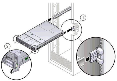
Description of "Figure 7-7 Inserting the Server with Mounting Brackets into the Slide Rails"Figure 7-7 callouts highlight the following:
1: Mounting bracket inserted into slide rail
2: Slide-rail release lever
-
Insert the mounting brackets into the slide rails, and push the server into the rack until the mounting brackets encounter the slide rail stops, approximately 30 cm (12 inches).
-
Simultaneously push down and hold the slide rail release levers on each mounting bracket while pushing the server into the rack.
-
Continue pushing until the slide rail locks on the front of the mounting brackets engage the slide rail assemblies, and you hear the click.
-
-
Cable the new server as described in "Cabling the Storage Servers".
Note:
Oracle recommends that two people push the servers into the rack: one person to move the server in and out of the rack, and another person to watch the movement of the cables and the CMA.
See Also:
"Installing the Server Into a Rack" in Sun Server X4-2L Installation Guide at
http://docs.oracle.com/cd/E36974_01/html/E38145/z4000087165586.html#scrolltoc
Cabling the Storage Servers
After installing the new storage servers, cable them to the existing equipment.
Note:
-
The existing cable connections in the rack do not change.
-
The blue cables connect to the compute servers, and the black cables connect to the storage servers. These network cables are for the NET0 Ethernet interface port.
-
Attach and route the management cables on the CMA and rear panel for one server at a time. Do not slide out multiple servers.
-
Start from the bottom of the rack, and work upward.
-
Longer hook and loop straps are needed when cabling three CAT5e cables or two twinaxial cables.
To cable the new servers in the rack:
-
Install the cable management arm (CMA):
-
Into the left slide rail, slide CMA connector A until it locks into place with an audible click.
-
Into the right slide rail, slide CMA connector B until it locks into place with an audible click. Then do the same with CMA connector C.
-
-
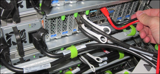
Insert the cables into their ports through the hook and loop straps, then route the cables into the CMA in this order:
-
Power
-
Ethernet
-
InfiniBand
-
-
Route the cables through the CMA and secure them with hook and loop straps on both sides of each bend in the CMA.
-
Close the crossbar covers to secure the cables in the straightaway.
-
Verify operation of the slide rails and the CMA for each server:
Note:
Oracle recommends that two people do this step: one person to move the server in and out of the rack, and another person to watch the movement of the cables and the CMA.
-
Slowly pull the server out of the rack until the slide rails reach their stops.
-
Inspect the attached cables for any binding or kinks.
-
Verify that the CMA extends fully from the slide rails.
-
-
Push the server back into the rack:
-
Release the two sets of slide rail stops.
-
Locate the levers on the inside of each slide rail, just behind the back panel of the server. They are labeled PUSH.
-
Simultaneously push in both levers and slide the server into the rack, until it stops in approximately 46 cm (18 inches).
-
Verify that the cables and CMA retract without binding.
-
Locate the slide rail release buttons near the front of each mounting bracket.
-
Simultaneously push in both slide rail release buttons and slide the server completely into the rack, until both slide rails engage.
-
-
Dress the cables, and then tie off the cables with the straps. Oracle recommends that you dress the InfiniBand cables in bundles of eight or fewer.
-
Slide each server out and back fully to ensure that the cables are not binding or catching.
-
Repeat the procedure for all servers.
-
Connect the power cables to the power distribution units (PDUs). Ensure the breaker switches are in the OFF position before connecting the power cables. Do not plug the power cables into the facility receptacles now.
See Also:
-
"Install the Second-Generation Cable Management Arm" in Sun Server X4-2L Installation Guide at
http://docs.oracle.com/cd/E36974_01/html/E38145/z40000151427029.html#scrolltoc
Closing the Rack
To close the rack after installing new equipment:
-
Replace the rack front and rear doors:
-
Retrieve the doors and place them carefully on the door hinges.
-
Connect the front and rear door grounding strap to the frame.
-
Close the doors.
-
(Optional) Lock the doors. The keys are in the shipping kit.
-
-
(Optional) Replace the side panels, if they were removed for the upgrade:
-
Lift each side panel up and onto the side of the rack. The top of the rack can support the weight of the side panel. Ensure that the panel fasteners line up with the grooves in the rack frame.
-
Turn each side panel fastener 1/4 turn clockwise using the side panel removal tool. Turn the fasteners next to the panel lock clockwise. There are 10 fasteners per side panel.
-
(Optional) Lock each side panel. The key is in the shipping kit. The locks are located on the bottom center of the side panels.
-
Connect the grounding straps to the side panels.
-
After closing the rack:
-
If you are installing a new system, proceed to "Installing the Software on Recovery Appliance"
-
If you added the server to increase storage on an existing system, proceed to "Making New Storage Available"
