18 Servicing the OCP Network Interface Card (FRU)

The following section describes how to service and install the Open Compute Project (OCP) version 3.0 (V3) Network Interface Card (NIC). The OCP V3 NIC is a field-replaceable unit (FRU). For more information about FRUs, see Illustrated Parts Breakdown and Field-Replaceable Units.

Caution:

The OCP NIC must be removed and replaced only by authorized Oracle Service personnel.

Caution:

Ensure that all power is removed from the server before removing or installing the OCP NIC. You must disconnect all power cables from the system before performing these procedures.

Caution:

These procedures require that you handle components that are sensitive to electrostatic discharge. This sensitivity can cause the component to fail. To avoid damage, ensure that you follow electrostatic discharge safety measures and antistatic practices. See Electrostatic Discharge Safety.

This section covers the following procedures:
Remove the OCP Network Interface Card

  1. Prepare the server for service.
    1. Power off the server and disconnect the power cords from the power supplies.
    2. Disconnect data cables from the OCP NIC QSFP ports (PORT 1 and PORT 2).
    3. Extend the server to the maintenance position.
    4. Attach an antistatic wrist strap to your wrist, and then to a metal area on the chassis.
    5. Remove the server top cover.
  2. Remove the following components:
    • Air baffles

      Note:

      You need to remove only the P1 rear air baffle from the server. All other air baffles can remain in the server.
    • Fan modules

      See Remove a Fan Module.

    • PCIe risers with attached PCIe cards

      See Servicing PCIe Risers (CRU).

      Note:

      You do not need to remove attached PCIe cards from risers, as it is necessary to lift only the PCIe risers from the server to disengage the attached PCIe card rear brackets from the server chassis.
    • Power supplies

      See Remove a Power Supply.

      Note:

      It is not necessary to completely remove the power supplies from the server; simply pull them out far enough to disengage them from the motherboard connectors.
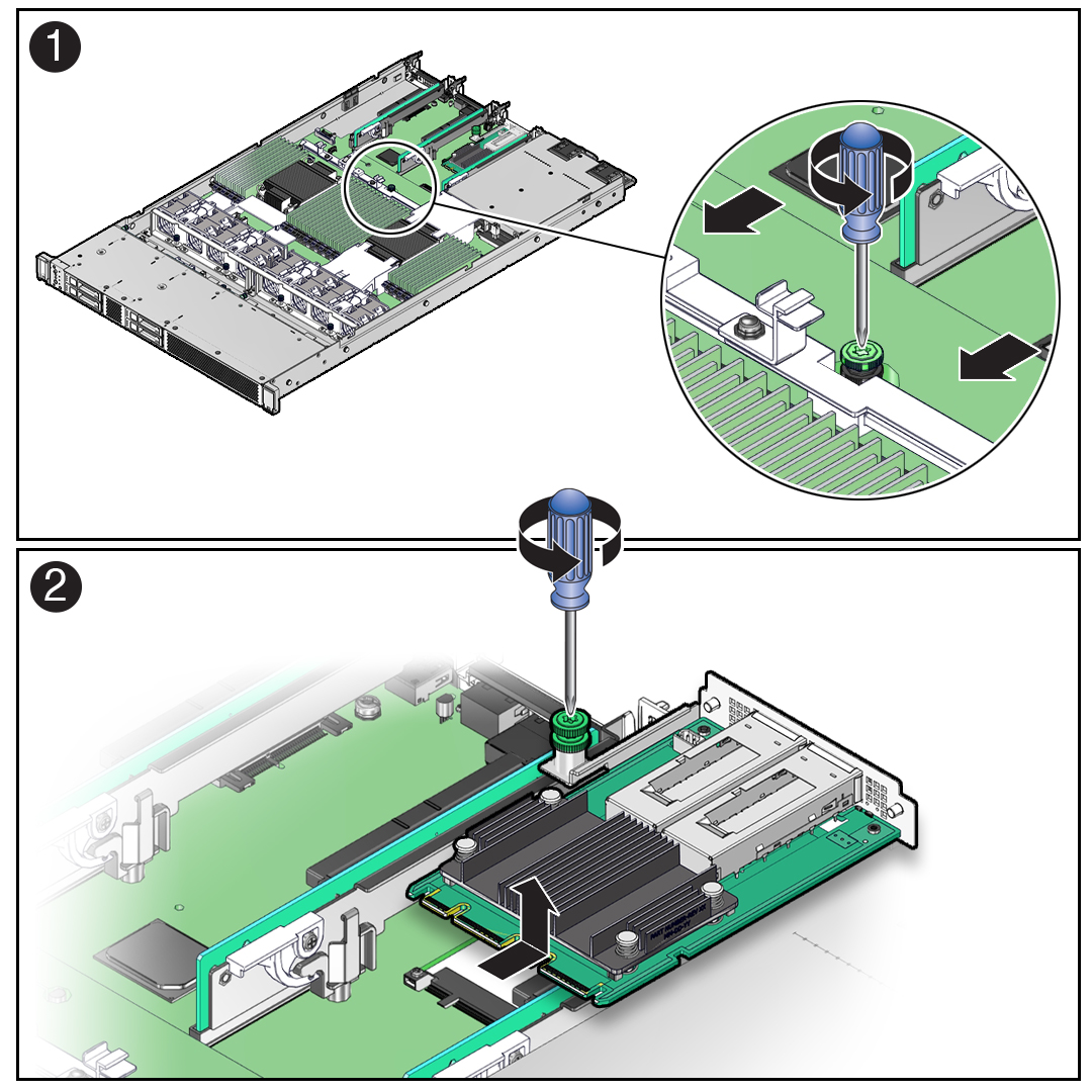
  3. Using a Torx T25 screwdriver, loosen the green captive screw that secures the motherboard to the server chassis [1].

    Figure showing the OCP NIC being removed from the server.
  4. Grasp the motherboard handle and the motherboard front finger loop, and slide the motherboard toward the front of the server until the OCP NIC QSFP connectors have cleared the rear panel cutouts [1].
  5. Using a Torx T25 screwdriver, loosen the green captive (retention) screw that secures the OCP NIC to the motherboard [2].
  6. Grasp the OCP NIC and pull it toward the rear of the chassis to disengage the OCP NIC connector from the motherboard connector slot [2].
  7. Lift the OCP NIC from the motherboard and out of the server chassis [2].

Install the OCP Network Interface Card

  1. Unpack the replacement OCP NIC.
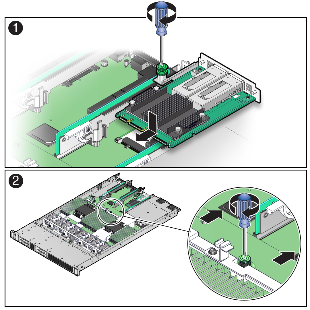
  2. Insert the OCP NIC into the server chassis [1].

    Figure showing the OCP NIC being installed in the server.
  3. Align the OCP NIC connector with the motherboard connector slot, and gently push the OCP NIC connector into the motherboard connector slot [1].
  4. Using a Torx T25 screwdriver, tighten the green captive (retention) screw to secure the OCP NIC to the motherboard [1].
  5. Grasp the motherboard handle and the motherboard front finger loop, and slide the motherboard toward the rear of the server until the OCP NIC QSFP connectors fit correctly into the rear panel cutouts [2].

    Note:

    Ensure that all indicators, controls, and connectors on the rear of the motherboard fit correctly into the rear panel cutouts.
  6. Using a Torx T25 screwdriver, tighten the green captive screw to secure the motherboard to the server chassis [2].
  7. Reinstall the following reusable components:
  8. Return the server to operation.
    1. Install the server top cover.
    2. Return the server to the normal rack position.
    3. Reconnect the data cables to the OCP NIC QSFP ports (PORT 1 and PORT 2).
    4. Reconnect the power cords to the power supplies, and power on the server.
    5. Verify that the System OK status indicator is lit.