18 Servicing NVMe Cables (FRU)

The following section describes how to service NVMe cables. NVMe cables are field-replaceable units (FRUs). For more information about FRUs, see Illustrated Parts Breakdown and Field-Replaceable Units.

Caution:

NVMe cables must be removed and replaced only by authorized Oracle Service personnel.

Caution:

The system supplies power to the cables even when the server is powered off. To avoid personal injury or damage to the server, you must disconnect power cords before servicing the cables.

Caution:

These procedures require that you handle components that are sensitive to electrostatic discharge. This sensitivity can cause the component to fail. To avoid damage, ensure that you follow electrostatic discharge safety measures and antistatic practices. See Electrostatic Discharge Safety.

This section covers the following procedures:

Remove NVMe Cables

  1. Prepare the server for service.
    1. Power off the server and disconnect the power cords from the power supplies.
    2. Extend the server to the maintenance position.
    3. Attach an antistatic wrist strap to your wrist, and then to a metal area on the chassis.
    4. Remove the server top cover.
    5. Remove the air baffle.
    6. Remove the fan modules.
    7. Remove the fan tray from the server.
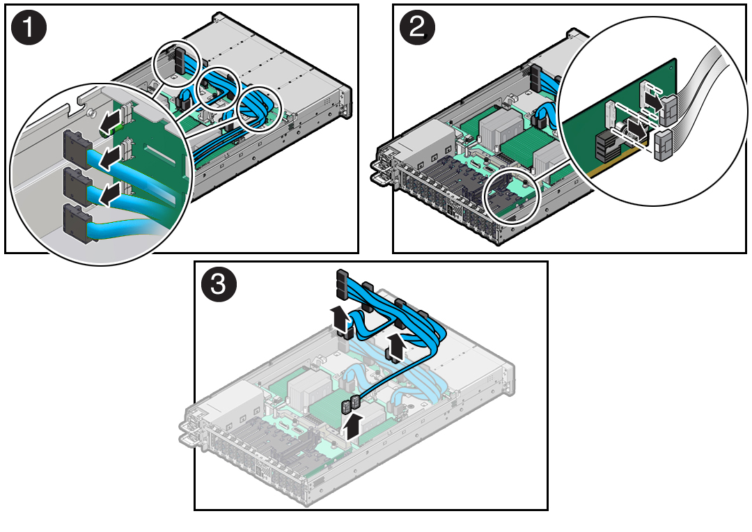
  2. Disconnect the NVMe cables from the disk backplane [1].

    Press and hold the green button on each connector to disengage the locking mechanism, then gently pull each connector from the disk backplane.


    Figure showing NVMe cables being removed from the server.
  3. If your storage drive configuration includes NVMe drives in slots 8 through 11, disconnect the NVMe cables from the Oracle Retimer card in PCIe slot 10 [2].

    Press and hold the green button on each connector to disengage the locking mechanism, and gently pull each connector to disengage them from the P0 and P1 connectors on the HBA. See also Remove a PCIe Card.

  4. Disconnect the NVMe cables from the motherboard NVMe connectors [3].

    Press and hold the green button on each connector to disengage the locking mechanism, and gently pull each connector to disengage them from the motherboard connectors.

  5. Remove the NVMe cables from the server [3].

    Carefully remove the NVMe cable bundles from the center and front left-side cable guides and the left-side cable trough. Be careful not to snag the cables on the server components.

Install NVMe Cables

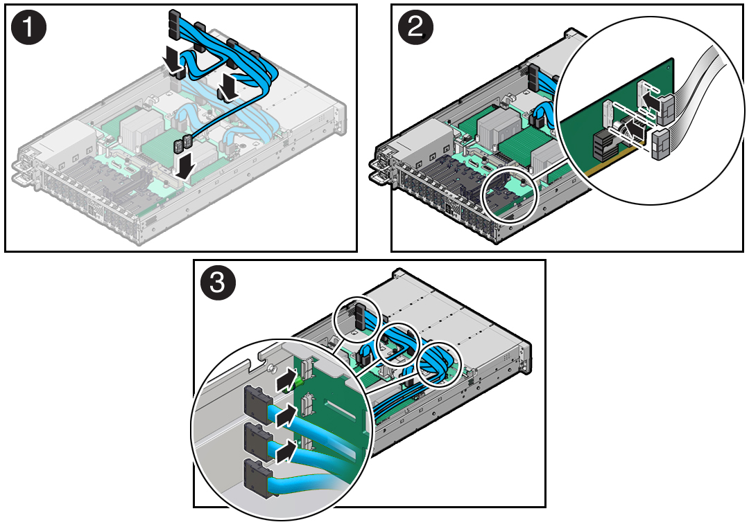
  1. Install the NVMe cables into the chassis.
    1. Install the NVMe cables for NVMe storage drives 0 through 7 between the disk backplane and motherboard NVMe connectors [1].
      • Route the NVMe cable bundles for NVMe storage drives 0, 1, 4, and 5 through the front left-side cable guide.

      • Route the NVMe cable bundles for NVMe storage drives 2, 3, 6, and 7 through the center cable guide.


      Figure showing NVMe cables being installed in the server.
    2. If your storage drive configuration includes NVMe drives in slots 8 through 11, install the NVMe cables between the disk backplane and the Oracle Retimer card in PCIe slot 10 [1].

      Route the NVMe cable bundles through the cable trough along the left side of the chassis.

  2. Reconnect the NVMe cables to the motherboard NVMe connectors, and if configured, the P0 and P1 connectors on the Oracle Retimer card in PCIe slot 10 [2].

    Plug each cable into its connector until you hear an audible click. To ensure proper NVMe cable connections, see the NVMe cable connections tables in Step 3. See also Install a PCIe Card.

  3. Reconnect the NVMe cables to the disk backplane [3].

    Plug each cable into its NVMe connector until you hear an audible click.

    Use the following tables to ensure proper NVMe cable connections.

    • NVMe storage drives 0 through 7

      Motherboard NVMe Connector Disk Backplane Connector Physical Storage Drive Slot Cable Part Number

      A/C (Left)

      A

      0

      7363958

      B

      4

      B

      C

      1

      8201505

      D

      5

      A/C (Right)

      E

      2

      7363958

      F

      6

      D

      G

      3

      8201506

      H

      7

    • NVMe storage drives 8 through 11

      Oracle Retimer Card NVMe Connector Disk Backplane Connector Physical Storage Drive Slot Cable Part Number

      P0

      J

      8

      8204031

      K

      9

      P1

      L

      10

      8204032

      M

      11

  4. Return the server to operation.
    1. Install the fan tray.
    2. Install the fan modules.
    3. Install the air baffle.
    4. Install the server top cover.
    5. Return the server to the normal rack position.
    6. Reconnect the power cords to the power supplies, and power on the server.
    7. Verify that the power supply AC OK LED is lit.
  5. Verify that NVMe cable connections are correct.

Verify NVMe Cable Connections

When NVMe cables are removed or replaced between the disk backplane and NVMe motherboard connectors and/or Oracle Retimer card, you must perform the procedure in this section to confirm that all NVMe cable connections are correct. If NVMe cable connections are not correct, the server operating system must not be allowed to boot, as it could cause a problem with disk drive mapping.

Before starting this procedure, ensure that the server is returned to operation. See Step 4 in Install NVMe Cables. This procedure requires access to the Oracle ILOM service processor (SP). The BIOS Setup Utility is used to halt the system so NVMe cable connection tests can be run for NVMe storage drives.

You can access the BIOS Setup Utility screens from the following interfaces:

  • Use a terminal (or terminal emulator connected to a computer) through the serial port on the back panel of the server.

  • Connect to the server using the Oracle ILOM Remote System Console Plus application.
  1. Power on the server.

    For example, to power on the server:

    • From the local server, press the On/Standby button on the front bezel.

    • From the Oracle ILOM web interface, click Host Management → Power Control and select Power On from the Select Action list.

    • From the Oracle ILOM CLI, type start /System

    The power-on self-test (POST) sequence begins.

  2. To enter the BIOS Setup Utility, press the F2 key (Ctrl+E from a serial connection) when prompted and while the BIOS is running the power-on self-tests (POST).

    This step halts the system so NVMe cable connection tests can be run for the NVMe storage drives.

  3. Open a terminal window. Using SSH (secure shell), log in to the Oracle ILOM command-line interface (CLI) on the server SP.
  4. To access the Oracle ILOM Diagnostic Shell, type the start /sp/diag/shell command, and click Enter.
  5. Type y to confirm that you want to start the Oracle ILOM Diagnostic Shell.

    The diag> prompt appears.

  6. To run the NVMe cable connection tests, type the hwdiag io nvme_test command, and click Enter.

    If any of the tests fail, there could be a problem with the cabling. For example:

    • If a cable is crossed (plugged into the incorrect port), then the NVMe drive DSN (Drive Serial Number) test would report two drives where the DSN does not match. The cabling for those drives must be inspected to ensure that it is correct.

    • If multiple NVMe drive PCIe links are not active, or multiple NVMe drive DSNs are not OK, check the Port 2 connection on the NVMe switch card. If Port 2 is incorrectly cabled, it could affect all three drives that are connected to that NVMe switch card.

  7. After the issues are resolved, power cycle the system by removing the power cords from the power supplies, wait 30 seconds, and reattach the power cords.
  8. Retest the system by repeating Step 1 through Step 6.

    After all NVMe cable connection tests pass, the server operating system can be booted.