| Skip Navigation Links | |
| Exit Print View | |

|
Oracle Java CAPS BPEL Designer and Service Engine User's Guide Java CAPS Documentation |
| Skip Navigation Links | |
| Exit Print View | |

|
Oracle Java CAPS BPEL Designer and Service Engine User's Guide Java CAPS Documentation |
BPEL Designer and Service Engine User's Guide
To View the Installed or Deployed JBI Components
The Composite Application Project
BPEL Designer and Service Engine Features
Supported WS-BPEL 2.0 Constructs
BPEL Service Engine and Oracle SOA Suite
Understanding the BPEL Module Project
Creating Sample Processes in the BPEL Designer
An Asynchronous Sample Process
Travel Reservation Service Sample
Creating a Sample BPEL Module Project
Navigating in the BPEL Designer
Element Documentation and Report Generation
Creating Documentation for an Element
Collapsing and Expanding Process Blocks in the Diagram
To Collapse and Expand a Process Block
Zooming In and Out of the Diagram
Printing BPEL Diagrams and Source Files
To Preview and Print a BPEL Diagram or Source File
Creating a BPEL Module Project
To Check the Status of the GlassFish V2 Application Server in the NetBeans IDE
To Register the GlassFish V2 Application Server with the NetBeans IDE
To Start the GlassFish V2 Application Server in the NetBeans IDE
Creating a new BPEL Module Project
To Create a BPEL Module Project
Creating the XML Schema and the WSDL Document
Creating a BPEL Process Using the BPEL Designer
Creating a Composite Application Project
To Create a New Composite Application Project
Building and Deploying the Composite Application Project
To Build and Deploy the Composite Application Project
Testing the Composite Application
Test the HelloWorldApplication Composite Application Project
Developing a BPEL Process Using the Diagram
Configuring Element Properties in the Design View
Finding Usages of BPEL Components
To Find Usages of a BPEL Component
The BPEL Designer Palette Elements
Adding BPEL Components to the Process
Using the Partner Link Element
Dynamic Partner Links and Dynamic Addressing
Using the CompensateScope Element
CompensateScope Element Properties
Adding an Else If Branch to the If Element
Adding an Else Branch to the If Element
Using the Repeat Until Element
Repeat Until Element Properties
Adding Branches to the Flow Element
Changing the Order of Elements inside Flow
Adding Child Activities to the Sequence
Changing the Order of Elements inside Sequence
To Open the BPEL Mapper Window
To Create a Mapping Without Using any Functions
To Use a Function in a Mapping
To Delete a Link or Function in a Mapping
Using Type Cast and Pseudo-Components
Type Cast and Pseudo Component Limitations
Using Normalized Message Properties
Using Normalized Message Properties in a BPEL Process
Using Predefined Normalized Message Properties in a BPEL Process
To Use Predefined Normalized Message Properties in a BPEL Process
Adding Additional Normalized Message Properties to a BPEL Process
To Add a Normalized Message Property Shortcut to a BPEL Process
To Edit an NM Property Shortcut
To Delete an NM Property Shortcut
To Add a Normalized Message Property to a BPEL Process
BPEL Code Generation Using NM Properties
General Normalized Message Properties
Binding Component Specific Normalized Message Properties
To Add a Compensation Handler to Scope or Invoke Elements
To Add a Termination Handler to Scope or Process Elements
Understanding Correlation. Using the Correlation Wizard
Elements That Use and Express Correlation
Defining Correlation Using the Correlation Wizard
BPEL Process Logging and Alerting
To Set the Log Level for the BPEL Service Engine
Configuring the BPEL Service Engine Runtime Properties
Accessing the BPEL Service Engine Runtime Properties
BPEL Service Engine Deployment Artifacts
Testing and Debugging BPEL Processes
To Add a Test Case and Bind it to a BPEL Operation
Steps in Debugging BPEL Processes
Starting and Finishing a BPEL Debugging Session
Using Breakpoints to Debug BPEL Processes
Group operations over breakpoints
Monitoring Execution of BPEL Processes
Correlation Sets and Faults information
BPEL Debugger Console Messages
Monitoring the BPEL Service Engine
Installing the BPEL Monitor API and Command Line Monitoring Tool
To Install the Monitoring Tool
Using the BPEL Monitor Command Line Tool
To Use the BPEL Monitor Command Line Tool
Configuring Quality of Service (QOS) Properties, Throttling, and Redelivery
Configuring the Quality of Service Properties
To Access the Config QOS Properties Editor
Configuring Message Throttling
Configuring an Endpoint for Throttling
Using Dynamic Partner Links and Dynamic Addressing
Using a Literal to Construct an Endpoint
Using an Existing Partner Link's Endpoint
Using an Incoming Message to Extract the Endpoint
Configuring Persistence for the BPEL Service Engine
Setting the JVM Classpath to the Database JDBC Drivers
To Set the GlassFish JVM Classpath Settings
Configuring the User and Database for Persistence
Creating an XA Connection Pool and a JDBC Resource
To Create an XA Connection Pool
Creating a Non-XA Connection Pool and JDBC Resource
Enabling Persistence for the BPEL Service Engine
To Enable Persistence for the BPEL Service Engine
Truncating and Dropping Tables
Configuring Failover for the BPEL Service Engine
Using BPEL Schemas Different from the BPEL 2.0 Specification
Relationship of Service Endpoint to Test Cases
GlassFish V2 Application Server HTTP Port
Travel Reservation Service Endpoint Conflict
Disabling Firewalls when Using Servers
Required Correlation Set Usage is Not Detected by the Validation System
When you are designing an application, you may need to configure certain services whose endpoints (addresses) are not known beforehand, or it may be necessary to change an endpoint reference while the application is running. The Dynamic Partner link feature allows you to dynamically assign an endpoint reference to the partner link. This means that you can use one partner link for subsequent calls to different web-services (provided that the services use the same interface).
There are several different ways to construct the end point information in BPEL. To deliver the address information to the partner link you can use standard a Assign activity and the BPEL Mapper. In the following examples the endpoint address follows the WS-Addressing schema. Refer to WS-Addressing standard (WS-A).
Note - Dynamic Addressing is only implemented for SOAP (HTTP Binding Component).
The BPEL literal syntax can be used to define an endpoint address and assign it to a partner link. The following code sample shows a BPEL literal used to define an HTTP endpoint assigned to a partner link.
<bpws:assign name="Assign2">
    <bpws:copy>
            <bpws:from>
                    <bpws:literal>
                            <sref:service-ref>
                                    <ns1:EndpointReference>
                                            <wsa:Address>
                                                http://localhost:8080/StockQuoteService
/StockQuotePort
                                            </wsa:Address>
                                            <wsa:ServiceName PortName="stockQuotePort">
                                                ns3:stockQuoteService>
                                            </wsa:ServiceName>
                                    </ns1:EndpointReference>
                            </sref:service-ref>
                       </bpws:literal>
                </bpws:from>
                bpws:to partnerLink="plStockQuote"/>
        </bpws:copy>
</bpws:assign>
In this scenario, you are invoking a partner link that is associated with a SOAP (HTTP) endpoint. That partner link, on the binding side of the application, acts as a proxy for BPEL to the external world.
In this example, we have an XML fragment that displays an Assign activity. The Assign has a copy and points to a literal address inline. When you invoke the service, you can assign a different address as a variable value in the invoke properties. In addition to assigning value to variable, you also assign a value to the partner link. Then, when the service is invoked, the HTTP Binding Component stops using the deployment address and instead uses the address that you just assigned.
The partner link "plStockQuote" could be subsequently used in an invoke.
Note that the WS-A defined schema object should be wrapped in an element called service-ref, that is defined in the BPEL. For more information about using the service-ref wrapper, refer to the BPEL Specification, section 6.3.
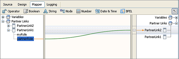
The endpoint of one partner link can be assigned to another partner link. The following BPEL Mapping and code sample show how the partnerRole endpoint of PartnerLink1 is copied to PartnerLink2.

Mapping the PartnerLink1 partnerRole to PartnerLink2 generates the following source code.
<assign name="Assign2">
     <copy>
         <from partnerLink="PartnerLink1" endpointReference="partnerRole"/>
         <to partnerLink="PartnerLink2"/>
     </copy>
 </assign>
In this example, PartnerLink1 is associated with a SOAP address. Instead of using that address, you want to use PartnerLink2. You send the address of PartnerLink1 to PartnerLink2. PartnerLink1 partnerRole endpoint is copied to PartnerLink2.
PartnerLink2 can also be used in subsequent invokes.
To extract an endpoint address from an incoming message, the message must be defined with the endpoint schema as part of the message. The following code sample show one way that this can be done.
<types>
    <xsd:schema targetNamespace="http://j2ee.netbeans.org/wsdl/dynamicPL">
        <xsd:import namespace="http://schemas.xmlsoap.org/ws/2004/08/addressing"
        schemaLocation="http://schemas.xmlsoap.org/ws/2004/08/addressing/"/>

    </xsd:schema>
</types>
<message name="dynamicPLOperationRequest">
    <part name="part1" element="wsa:EndpointReference"/>
</message>
Note that the prefix wsa is defined to point to http://schemas.xmlsoap.org/ws/2004/08/addressing.
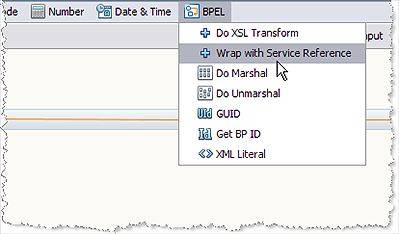
Use this message variable to assign the endpoint to a partner link at runtime. A special BPEL mapper function, "Wrap with Service Reference" makes it easy to map the WS-A message to a partner link, as demonstrated below.

Choosing the BPEL Mapper option Wrap with Service Reference adds the doXslTransform method box to the Mapper canvas.

The doXslTransform Method box generates the BPEL doXslTransform() function, as shown in the code sample below.
<assign name="Assign1">
    <copy>
        <from>ns0:doXslTransform('urn:stylesheets:wrap2serviceref.xsl',
$DynamicPLOperationIn.part1)</from>
        <to partnerLink="PartnerLink1"/>
    </copy>
</assign>
The stylesheet for the transformation is already defined by the editor.
Expanding on the last example, you can also have a BPEL service do a dynamic addressing invocation, with the address coming from a database.
You start with a composite application that is triggered by something such as a input file. You do not want to use the address that is directly assigned to the file, so you do a database query or database select for the address.
The composite application triggers the Database Binding Component to do a simple select from a table that contains addresses. The composite application takes the results from the database query and puts it into the BPEL Mapper and maps the query result to the variable where you normally put your dynamic SOAP address. The Mapper assigns this address to the partner link.
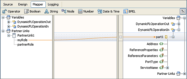
A service can send its own endpoints, that can then be used as call back addresses, using the following type of mapping.

The PartnerLink1 myRole is mapped to the DynamicPLOperationIn part1. This generates the following code sample.
<assign name="Assign2">
    <copy>
        <from partnerLink="PartnerLink1" endpointReference="myRole"/>
        <to variable="DynamicPLOperationIn" part="part1"/>
    </copy>
</assign>
When the variable “DynamicPLOperationIn” is used in subsequent invokes in the BPEL, the endpoint information is passed on to the partner.
Note - The BPEL Specification states that only the partner address can be changed dynamically. In BPEL terms, this means that only the partnerRole of a partner link can be assigned a value, and myRole does not change after the BPEL process has been deployed.