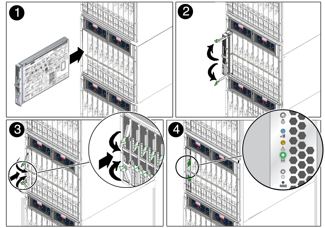
Insert the Server Module Into the Chassis
There are limitations on the total number of server modules that you can install in a modular system. Refer to the SPARC T5-1B Server Module Product Notes, Configuring Server Module Power Usage for details.
- If you have not done so, prepare the modular system and server module.
- If you have not done so, install any optional components.
- Remove the protective cover from the rear connector of the server module.
- Be prepared to communicate with
the server module after completing the physical installation.
As soon as you insert the server module in a powered modular system, power is supplied to the server module and the SP generates messages. If you want to see these messages, be ready to connect using one of the methods in Plan Communication With the Server Module During Installation.
- Locate the slot in the chassis
where you plan to install the server module.
A filler panel should remain in this slot until just before you are ready to insert the server module. All slots should remain filled with server modules or filler panels to ensure correct air flow, heat, and electromagnetic interference conditions in the modular system.
- Remove the filler panel from
the selected chassis slot.
Pull down the ejector arm of the filler panel, then pull the panel straight out of the chassis.

Caution - Be ready to insert the server module within 60 seconds of removing the filler panel.
- Use both hands to position the
server module vertically with the ejector arms on the right (panel
1).

- Push the server module into the empty slot until the module extends about 0.5 inch (1.5 cm) from the chassis front (panel 2).
- Pinch the ejector levers to open them (panel 2).
- Push the server module into the chassis and close the ejector levers (panels 2 and 3).
- Monitor status messages when
power is applied to the server module (panel 4).
When the server module is plugged in, standby power is supplied to the SP. After about 10 seconds, the front panel LEDs blink three times, then the green OK LED blinks for a few minutes. The server module SP generates messages as soon as the server module is connected to a powered modular system. See Front and Rear Panel Components.
- Power on the server module.