| Skip Navigation Links | |
| Exit Print View | |

|
Oracle® ZFS Storage Appliance Administration Guide |
Chapter 1 Oracle ZFS Storage Appliance Overview
Chapter 3 Initial Configuration
Chapter 4 Network Configuration
Network IP MultiPathing (IPMP)
Network Performance and Availability
Network Configuration Using the BUI
Network Configuration Using the CLI
Network Configuration Tasks Using the BUI
Creating a single port interface
Creating a single port interface, drag-and-drop
Creating an LACP aggregated link interface
Creating an IPMP group using probe-based and link-state failure detection
Creating an IPMP group using link-state only failure detection
Creating an InfiniBand partition datalink and interface
Creating a VNIC without a VLAN ID for clustered controllers
Creating VNICs with the same VLAN ID for clustered controllers
Network Configuration Tasks Using the CLI
Changing the multihoming property to strict
Chapter 5 Storage Configuration
Chapter 6 Storage Area Network Configuration
Chapter 8 Setting ZFSSA Preferences
Chapter 10 Cluster Configuration
Chapter 12 Shares, Projects, and Schema
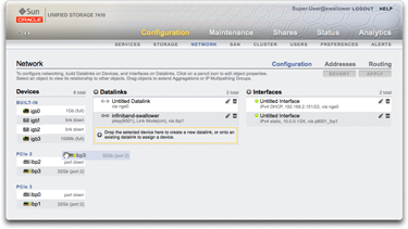
In ZFSSA model, network devices represent the available hardware - they have no configurable settings. Datalinks are a layer 2 entity, and must be created to apply settings such as LACP to these network devices. Interfaces are a layer 3 entity containing the IP settings, which they make available via a datalink. This model has separated network interface settings into two parts - datalinks for layer 2 settings, and interfaces for layer 3 settings.
Figure 4-1 Network Configuration Window

An example of a single IP address on a single port (common configuration) is:
|
The following configuration is for a 3-way link aggregation:
|
The datalink entity (which we named "aggr1") groups the network devices in a configurable way (LACP aggregation policy). The interface entity (which we named "phobos") provides configurable IP address settings, which it makes available on the network via the datalink. The network devices (named "igb1", "igb2", ..., by the system) have no direct settings. Datalinks are required to complete the network configuration, whether they apply specific settings to the network devices or not.