Overview of Oracle ZFS Storage Appliance Racked System ZS5-4
The Oracle ZFS Storage Appliance Racked System ZS5-4 is a pre-racked and pre-cabled system comprising two clustered ZS5-4 controllers and up to eight DE3-24C disk shelves in the base cabinet. Up to three expansion cabinets with up to ten DE3-24C disk shelves each can be connected to the base cabinet, for a total of 38 disk shelves.
Configurations are offered in multiples of two disk shelves, as well as half-rack expansion: 2 disk shelves (minimum), 4, 6, 8, 10, 12, 13 (half rack), 14, 16, 18, 20, 22, 23 (half rack), 24, 26, 28, 30, 32, 33 (half rack), 34, 36, and 38 (maximum). Each ZS5-4 controller supports two, three, or four SAS HBA cards. However, four SAS HBA cards must be installed in each ZS5-4 controller to support disk shelves in the expansion cabinet(s).
If the clustered ZS5-4 controllers contain four SAS HBAs each, they support a high-availability configuration of:
-
Two chains of four disk shelves per disk chain in the base cabinet for a total of eight disk shelves, and
-
One to three expansion cabinets, each cabinet supporting two chains with a maximum of five disk shelves per disk chain, for a total of 10 disk shelves for one expansion cabinet, 20 disk shelves for two expansion cabinets, or 30 disk shelves for three expansion cabinets.
The base cabinet is self-contained and pre-cabled following the required cabling methodology. The section "Cabling Tables and Diagrams" describes how pre-racked systems are cabled, as well as how to expand your system in the future.
Each cabinet contains 42 rack units (RUs), with RU01 on the bottom. Each ZS5-4 controller occupies three rack units, and its location is referenced by the bottommost rack unit number. The top controller is referred to as Controller 1 and is located in RU20 in the base cabinet, and the bottom controller is Controller 0 in RU17. The following figure shows the slot number for each HBA card, as well as the port numbers in each card.
Figure 618 ZS5-4 HBA Slot Numbers (Back View)

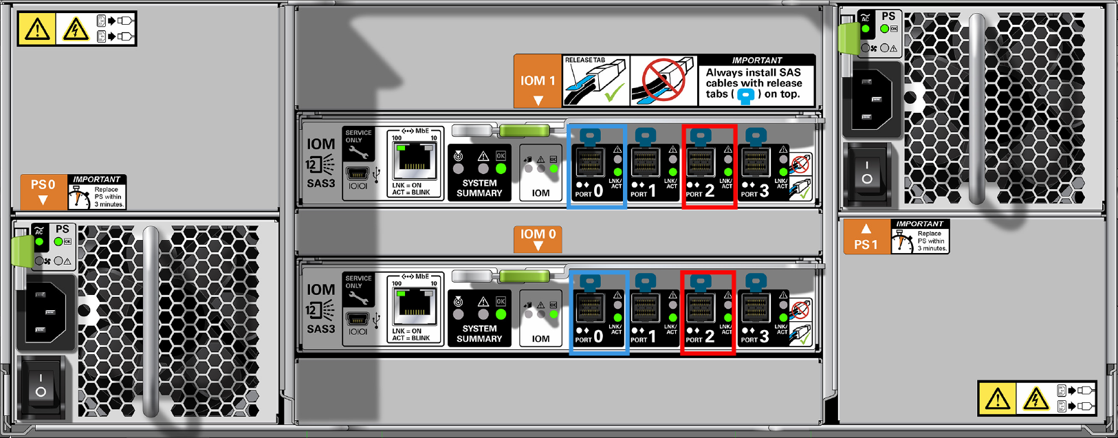
Each DE3-24C disk shelf occupies four rack units, and disk shelves are normally installed from the bottom of the cabinet to the top for stability. To provide higher performance capabilities, disk chains are alternated from the bottom to the top of the base cabinet, with four disk shelves per chain and gaps between components. Therefore, the first disk shelf is in RU01, the second in RU05, the third in RU23, the fourth in RU27, the fifth in RU09, and so on in an alternating manner. As shown in the following figure, the DE3-24C disk shelf has two I/O Modules (IOMs) with four ports each. In all cabling configurations, Port 1 and Port 3 are never used.
Figure 619 DE3-24C HBA Connections (Back View)
