Base Cabinet Configurations
ZS5-2 Racked System All Flash maximum performance configurations require two SAS-3 HBA cards; therefore, it provides a maximum of eight ports of SAS-3 HBA connectivity.
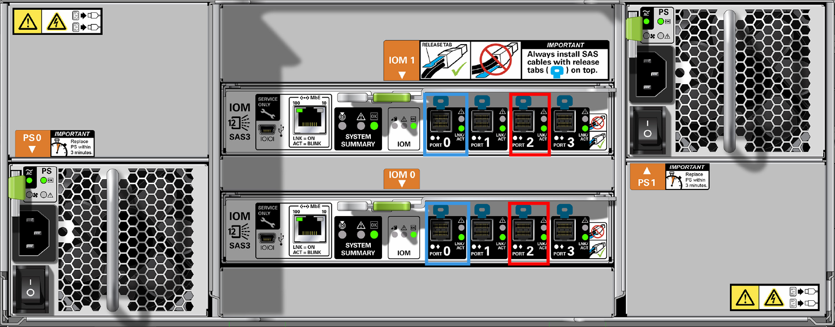
The SAS-3 HBA port numbering order is ascending, from bottom (Port 0) to top (Port 3). Both SAS-3 HBA cards and DE3-24 disk shelves use the SFF 8644 connectors.
Figure 610 ZS5-2 HBA Slot Numbers (Back View)

Figure 611 DE3-24P HBA Connections (Back View)

Figure 612 DE3-24C HBA Connections (Back View)
The ZS5-2 Racked System All Flash cabling configurations follow standard cabling methodologies with additional restrictions that allow use of the cable management arm (CMA). It provides a more practical implementation for SSD log device and read cache device matching, and can be structured for maximum or optimal performance.
Any upgrades that change the number of SAS-3 HBA cards, or include more than one cabinet that is not an original ZS5-2 Racked System All Flash system or not compatible with ZS5-2 Racked System All Flash have to be re-cabled for that particular configuration. For cabling examples of connecting DE3-24 disk shelves to ZS5-2 with 4x4 port SAS-3 HBAs, see Cabling DE3-24 Disk Shelves to ZS5-2 Controllers. For SAS cable length guidelines, see Cabinet and Cabling Guidelines.
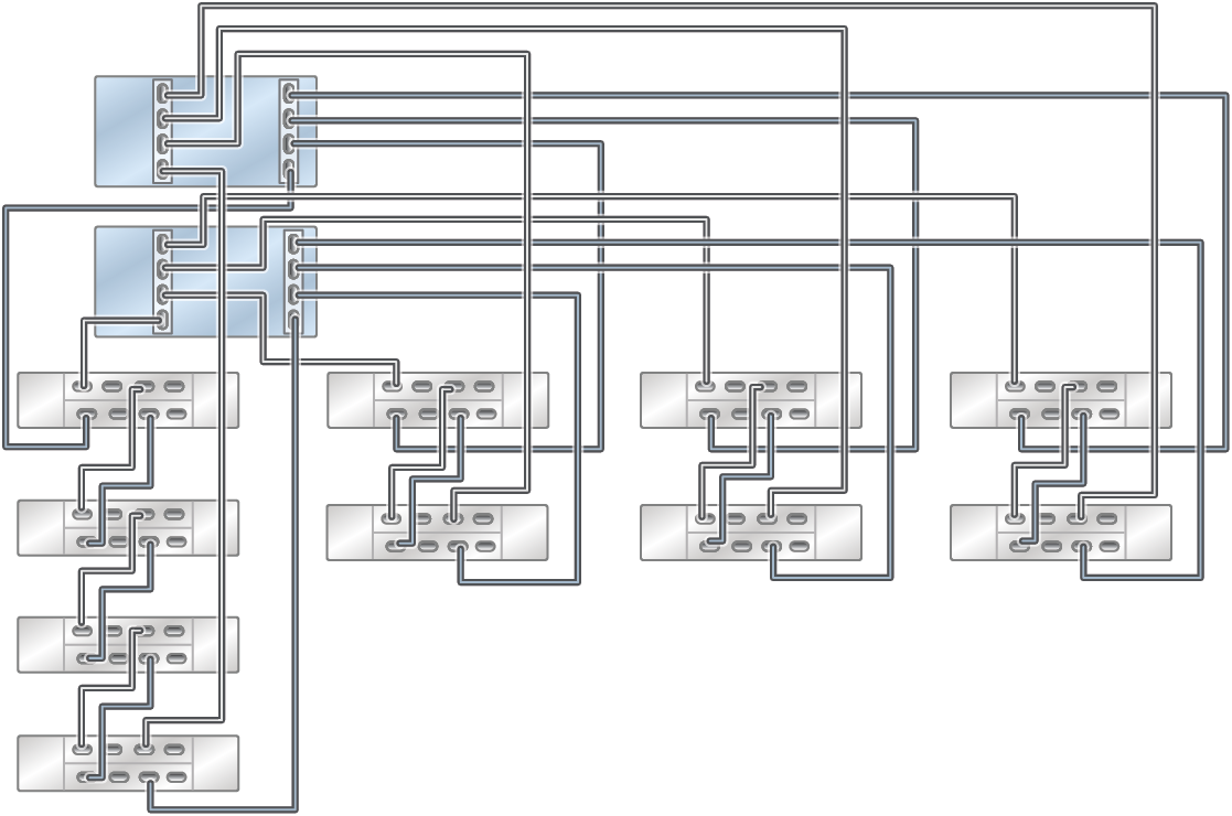
The base cabinet is self-contained and pre-cabled following the required cabling methodology. The following diagrams describe how the five base cabinet options are cabled.
Figure 613 ZS5-2 Racked System All Flash with four DE3-24P disk shelves in four chains
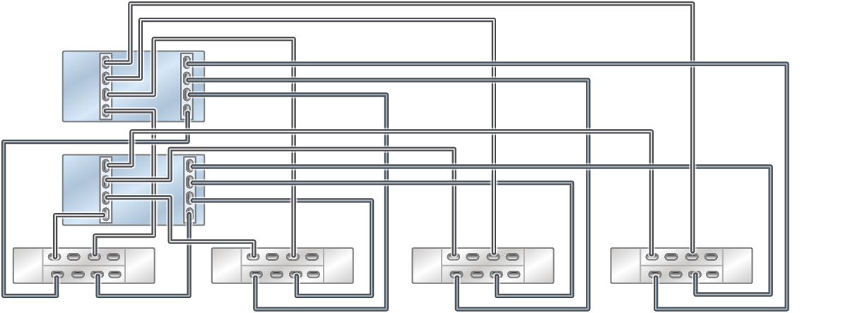
Figure 614 ZS5-2 Racked System All Flash with 16 DE3-24P disk shelves in four chains
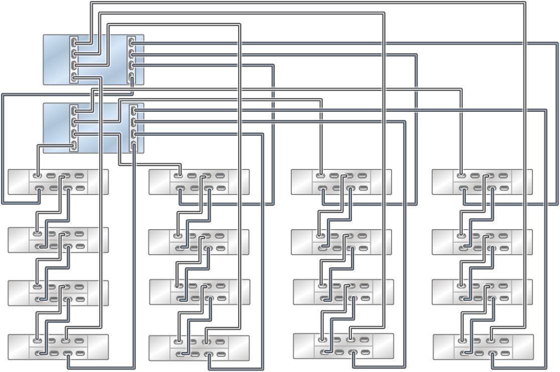
Figure 615 ZS5-2 Racked System All Flash with two DE3-24C (bottom left) and 12 DE3-24P disk shelves in four chains
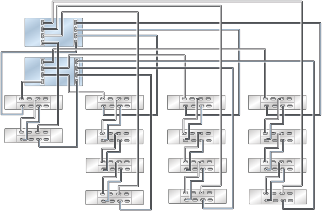
Figure 616 ZS5-2 Racked System All Flash with four DE3-24C (bottom left) and eight DE3-24P disk shelves in four chains
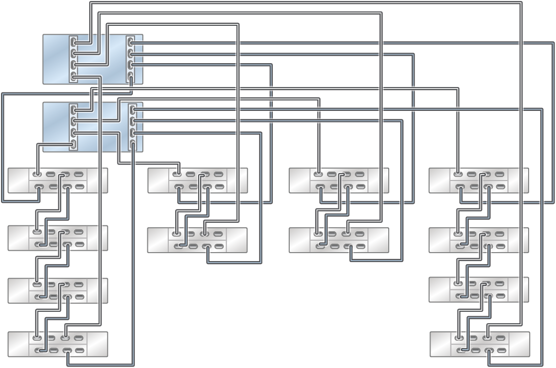
Figure 617 ZS5-2 Racked System All Flash with six DE3-24C (first two chains from the left) and four DE3-24P disk shelves in four chains
