
This section shows the external Ethernet connectivity of Oracle PCA.
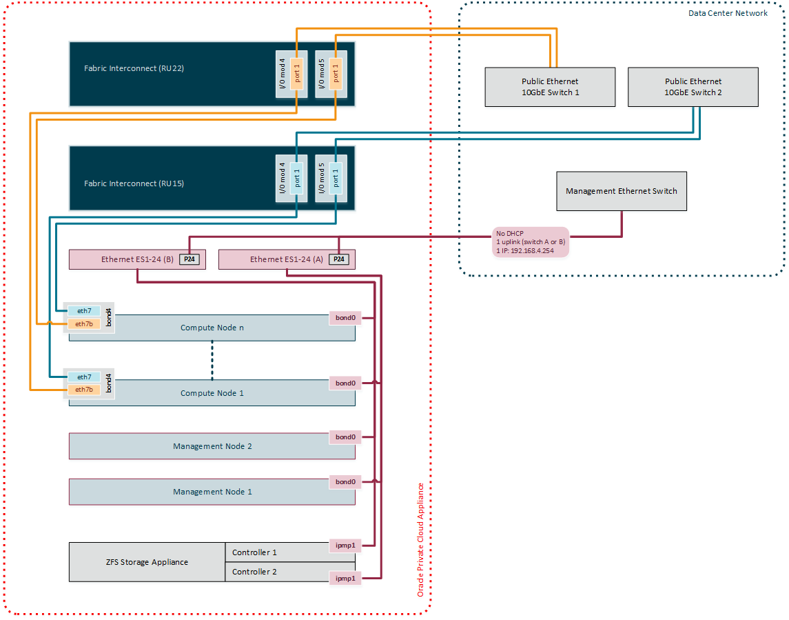
The connections in red in the left half of the diagram correspond with the out-of-band appliance management network
192.168.4.0/24. These are physical Ethernet ports connected with Ethernet cables to the two internally interconnected Oracle Switch ES1-24 switches. All appliance components and their ILOMs have a reserved IP address in this network. Only one address is available for customer use:192.168.4.254.You may connect to this management Ethernet network by choosing one of these methods:
Connect a workstation with an Ethernet cable plugged directly into the available port 19 in an Oracle Switch ES1-24. Statically assign IP address
192.168.4.254.Connect port 24 in one Oracle Switch ES1-24 – never both – to an Ethernet switch in your data center network. Use a workstation connected to the data center network and statically assign the IP address
192.168.4.254. Make sure that the management Ethernet switch used in this connection is configured to prevent DHCP leakage to the192.168.4.0/24subnet used by Oracle PCA.
The connections in gold and blue on the left hand side of the diagram correspond with the default network
vm_public_vlan. This is the standard VLAN-enabled network for virtual machine traffic with public access. The compute node connections are bonds of two Ethernet vNICs that terminate on port 1 of the I/O modules 4 and 5 in both Fabric Interconnects. The underlying physical connection consists of redundant InfiniBand cabling. The physical 10GbE ports of the Fabric Interconnects are connected for redundancy to two next-level data center switches.The vNIC connections are distributed across the Fabric Interconnects and the I/O modules for maximum availability. If one of the redundant components fails at any level, be it an I/O module, an entire Fabric Interconnect or a next-level switch in the data center, the VMs always maintain an active external connection using either a blue or a red path. The uplinks to the data center switches are deliberately not cross-cabled to prevent that half of the compute nodes lose external connectivity if one of those switches fails.
All custom public networks follow the same principle as the default
vm_public_vlanshown in this diagram. However, for the custom networks additional bonded vNICs are created on the compute nodes, and additional I/O ports must be configured and cabled.