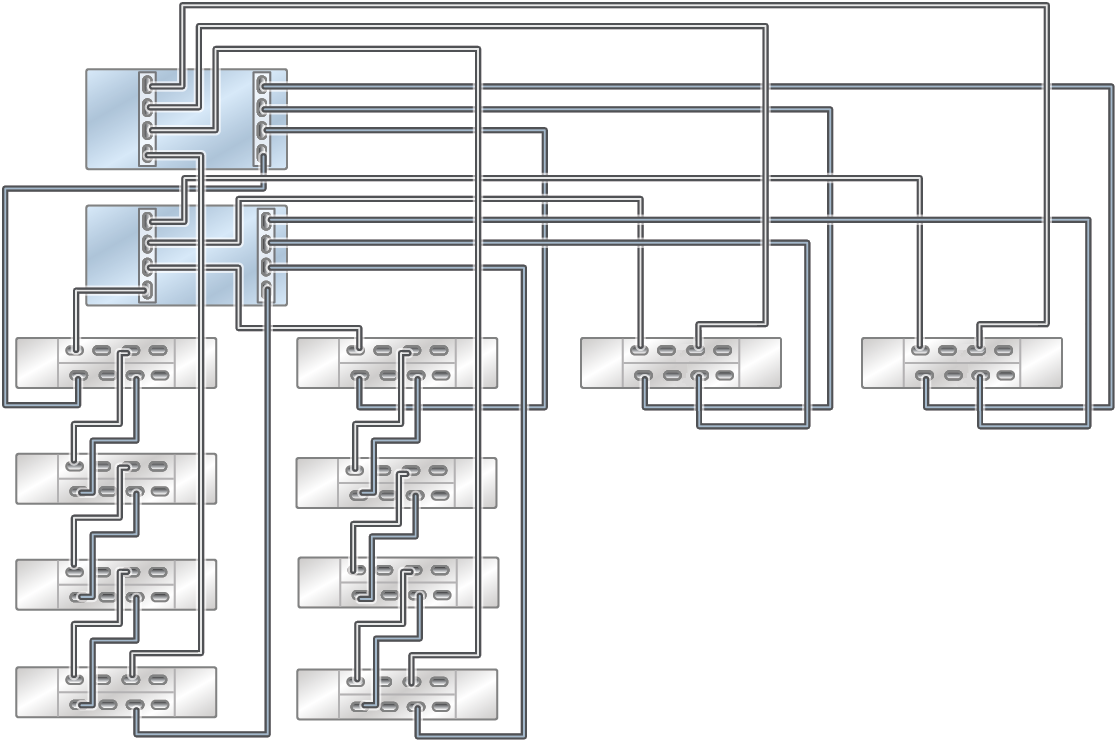
All-Flash/Mixed Configurations for ZS7-2 MR Racked Systems
This section provides an overview and cabling diagrams for ZS7-2 MR Racked Systems consisting of all-flash/mixed configurations with either all DE3-24P disk shelves or a mix of DE3-24P and DE3-24C disk shelves. High-performance DE3-24P disk shelves comprise either 20 or 24 all-flash SSDs, or 20 or 24 high-speed hard disk drives. Some configurations include read cache and/or log devices. Maximum performance configurations support DE3-24P disk shelves, while optimum performance configurations support both DE3-24P and DE3-24C disk shelves. Some configurations do not support expansion cabinets.
This section contains the following topics:
-
Overview of ZS7-2 MR Racked System All-Flash/Mixed Configurations
-
Base Cabinet Configurations for ZS7-2 MR Racked System All-Flash/Mixed Configurations
Overview of ZS7-2 MR Racked System All-Flash/Mixed Configurations
All-Flash/Mixed configurations take advantage of DE3-24P high-performance disk shelves and are available in a base cabinet, or a base cabinet with up to one expansion cabinet for some configurations. Six base cabinet options are offered in a total of 27 possible system configurations, and all base cabinet options contain two ZS7-2 MR controllers.
ZS7-2 MR Racked System maximum performance configurations feature up to four Oracle Storage Drive Enclosure DE3-24P disk shelves in the base cabinet. The disk shelves are configured as one single shelf per chain to obtain maximum performance. Depending on the number of chains in the base cabinet, ZS7-2 MR Racked System maximum performance configurations can support one expansion cabinet.
|
ZS7-2 MR Racked System optimum performance configurations feature up to 16 Oracle Storage Drive Enclosure DE3-24P disk shelves (configured as four shelves per chain), as well as various combinations of Oracle Storage Drive Enclosure DE3-24C and DE3-24P disk shelves in the base cabinet. Depending on the number of chains in the base cabinet, ZS7-2 MR Racked System optimum performance configurations can support up to one expansion cabinet.
|
The ZS7-2 MR Racked System all-flash/mixed configurations support various storage options.
|
Base Cabinet Configurations for ZS7-2 MR Racked System All-Flash/Mixed Configurations
ZS7-2 MR Racked System all-flash/mixed configurations have two SAS-3 HBAs in each controller, which provide the maximum of eight ports of SAS-3 HBA connectivity.
The SAS-3 HBA port numbering order is ascending, from bottom (Port 0) to top (Port 3). Both SAS-3 HBA cards and DE3-24 disk shelves use the SFF 8644 connectors.
The following figure shows the slot number for each HBA card, as well as the port numbers in each card.
Figure 663 ZS7-2 MR Controller HBA Slot Numbers (Back View)

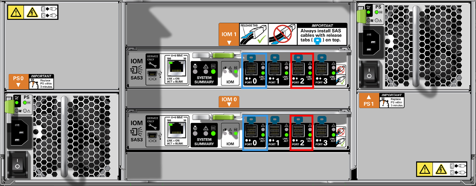
As shown in the following figure, the DE3-24P disk shelf has two I/O modules (IOMs) with four ports each. In all cabling configurations, Port 1 and Port 3 are never used.
Figure 664 DE3-24P Disk Shelf HBA Connections (Back View)

As shown in the following figure, the DE3-24C disk shelf has two I/O modules (IOMs) with four ports each. In all cabling configurations, Port 1 and Port 3 are never used.
Figure 665 DE3-24C Disk Shelf HBA Connections (Back View)
The ZS7-2 MR Racked System cabling configurations follow standard cabling methodologies with additional restrictions that allow use of the cable management arm (CMA). They provide a more practical implementation for SSD log device and read cache device matching, and can be configured for maximum or optimal performance.
Any upgrades that change the number of SAS-3 HBA cards, or include more than one cabinet that is not an original ZS7-2 MR Racked System or not compatible with ZS7-2 MR Racked System must be re-cabled for that particular configuration. For cabling examples of connecting DE3-24 disk shelves to a ZS7-2 MR controller with 4x4 port SAS-3 HBAs, see Cabling DE3-24 Disk Shelves to ZS7-2 Mid-range (MR) Controllers. For SAS cable length guidelines, see Cabinet and Cabling Guidelines.
The cabinets are self-contained and pre-cabled following the required cabling methodology. The following diagrams illustrate how the six base cabinet options are cabled.
Figure 666 ZS7-2 MR Racked System Performance Configuration: Four DE3-24P Disk Shelves (maximum performance)
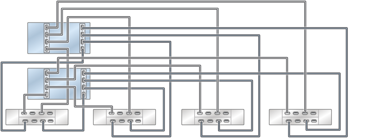
This configuration can have one, two, or four DE3-24P disk shelves utilizing the maximum performance cabling scheme.
Figure 667 ZS7-2 MR Racked System Performance Configuration: 16 DE3-24P Disk Shelves (optimum performance)
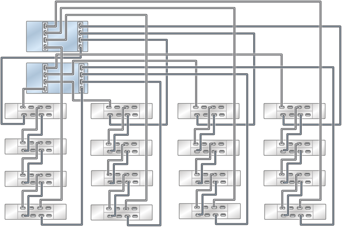
DE3-24P disk shelves in this configuration are added in pairs. Any other combination of disk shelves are added by pairs starting at the bottom of the rack. Valid disk shelf count combinations are 2, 4, 6, 8, 10, 12, 14, and 16 disk shelves.
Figure 668 ZS7-2 MR Racked System Performance Configuration: Two DE3-24C (bottom left) and Two DE3-24P to 14 DE3-24P Disk Shelves (optimum performance)
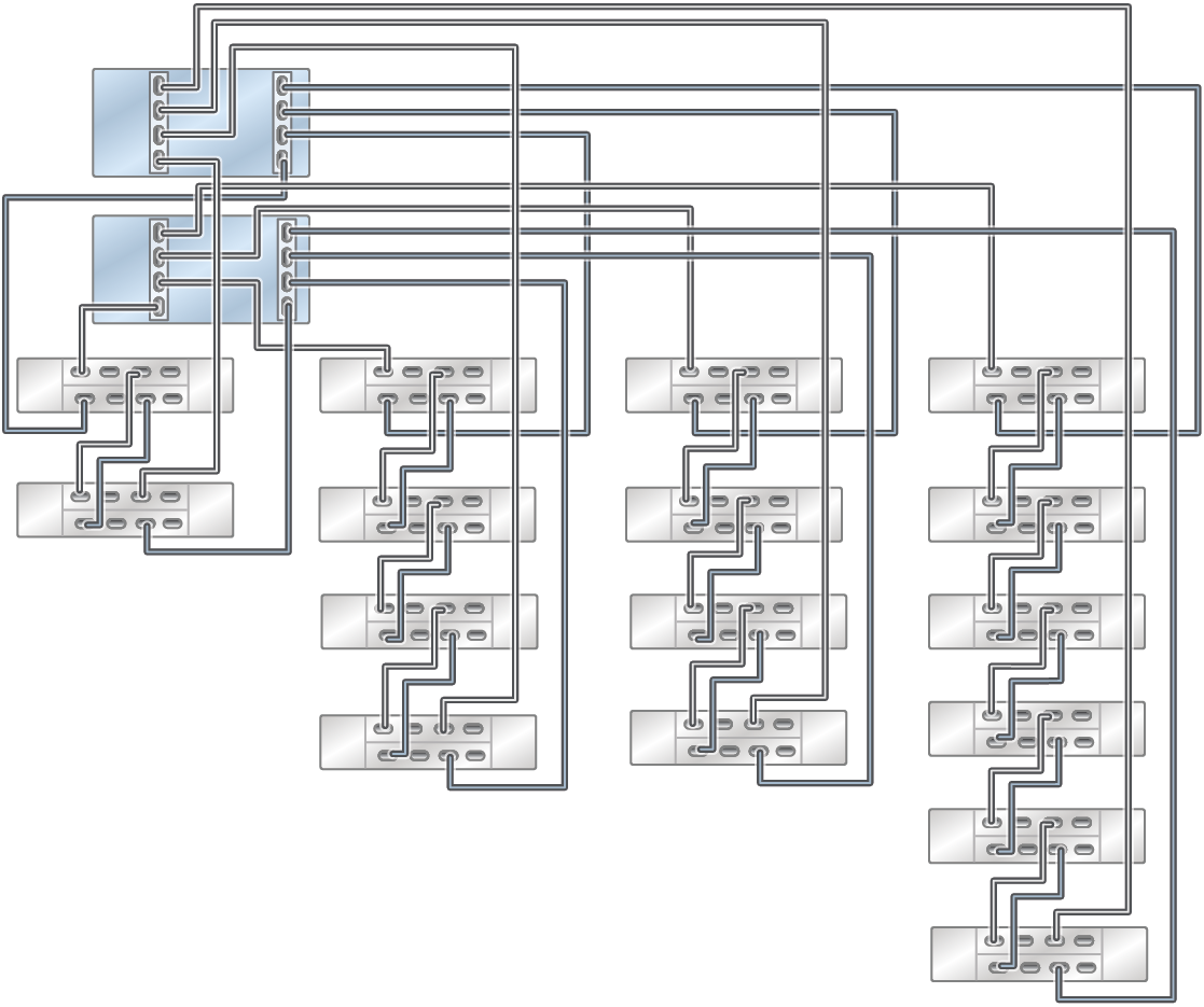
DE3-24P disk shelves in this configuration are added in pairs. Any other combination of disk shelves are added by pairs starting at the bottom of the rack. Valid disk shelf count combinations are 2, 4, 6, 8, 10, 12, 14, and 16 disk shelves.
Figure 669 ZS7-2 MR Racked System Performance Configuration: Four DE3-24C (bottom left) and Two DE3-24P to Ten DE3-24P Disk Shelves (optimum performance)
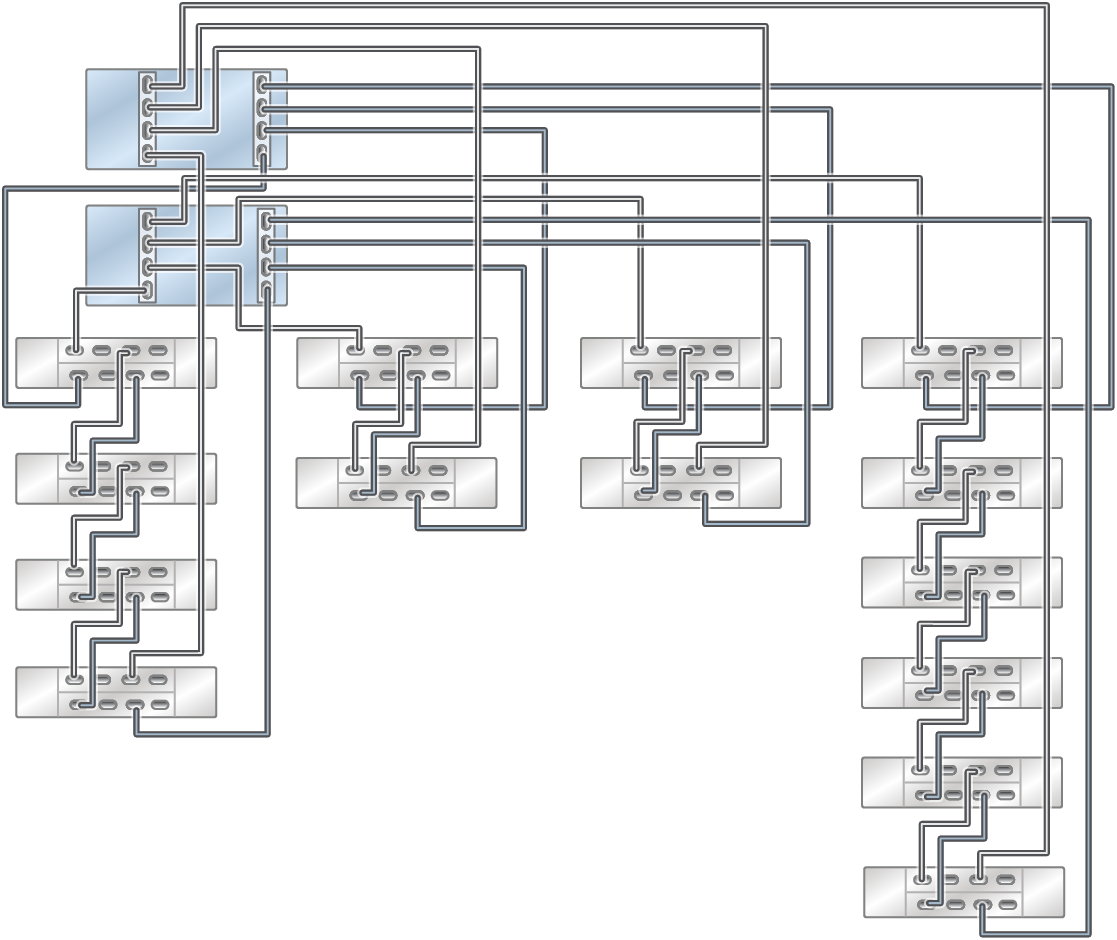
Figure 670 ZS7-2 MR Racked System Performance Configuration: Six DE3-24C (first two chains from the left) and Two DE3-24P to Six DE3-24P Disk Shelves (optimum performance)
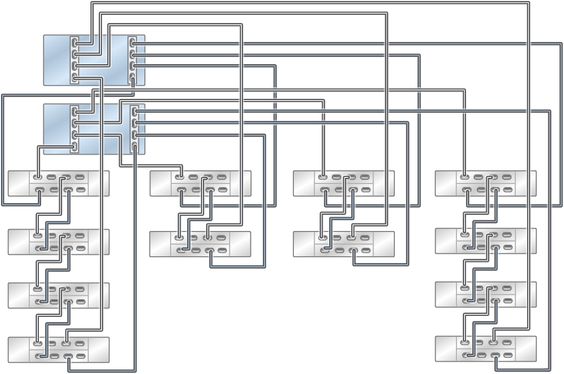
Figure 671 ZS7-2 MR Racked System Performance Configuration: Eight DE3-24C (first two chains from the left) and Two DE3-24P Disk Shelves (optimum performance)
