Capacity Configurations for ZS7-2 MR Racked Systems
This section provides an overview and cabling diagrams for ZS7-2 MR Racked System capacity configurations.
This section contains the following topics:
Overview of ZS7-2 MR Racked System Capacity Configurations
Capacity configurations take advantage of high-capacity disk shelves and are available in a base cabinet, or a base cabinet with one expansion cabinet. Two ZS7-2 MR controllers and up to 16 Oracle Storage Drive Enclosure DE3-24C disk shelves can be supported, as shown in the following table. Note that the total number of disk shelves for the base cabinet and the expansion cabinet together cannot exceed 16.
|
Each ZS7-2 MR controller supports two SAS HBA cards. Two SAS HBA cards must be installed in each ZS7-2 MR controller to support disk shelves in the expansion cabinet.
Each ZS7-2 MR controller has two SAS HBA cards. Clustered ZS7-2 MR controllers support a high-availability configuration consisting of:
-
Base cabinet: Two chains with four disk shelves in one chain and five disk shelves in the other chain for a total of nine disk shelves, and
-
Expansion cabinet: Two chains with four disk shelves in one chain and one of three disk shelves in the other chain for a total of seven disk shelves.
The cabinets are self-contained and pre-cabled following the required cabling methodology. Pre-racked system cabling tables and diagrams, which can also be used for planning future system expansion, are provided in the section Cabling Tables and Diagrams for ZS7-2 MR Racked System Capacity Configurations.
Each cabinet contains 42 rack units (RUs), with RU01 on the bottom. Each ZS7-2 MR controller occupies two rack units, and its location is referenced by the bottommost rack unit number. The top controller is referred to as Controller 1 and is located in RU20 in the base cabinet; the bottom controller is Controller 0 in RU17. Because the ZS7-2 MR controller occupies two rack units, the base cabinet contains a filler panel above each controller so the cabinet layout is similar to prior offerings of Oracle racked systems with three-rack-unit controllers. It also allows for better serviceability access and cabling through the rear CMA. The following figure shows the slot number for each HBA card, as well as the port numbers in each card.
Figure 656 ZS7-2 MR Controller HBA Slot Numbers (Back View)

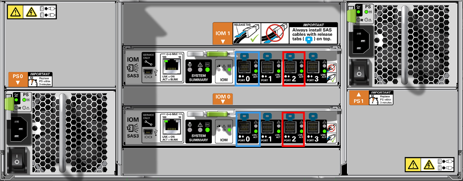
Each DE3-24C disk shelf occupies four rack units, and disk shelves are normally installed from the bottom of the cabinet to the top for stability. As shown in the following figure, the DE3-24C disk shelf has two I/O Modules (IOMs) with four ports each. In all cabling configurations, Port 1 and Port 3 are never used.
Figure 657 DE3-24C Disk Shelf HBA Connections (Back View)
Cabling Tables and Diagrams for ZS7-2 MR Racked System Capacity Configurations
The following table describes the locations and port connections for two controllers and nine disk shelves in the base cabinet, using 3-meter optical SAS cables. The first disk shelf is located in RU01, and each disk shelf has two IOMs.
Note - The following tables are for a full base rack configuration consisting of two chains, and an expansion rack configuration consisting of two chains.
| ||||||||||||||||||||||||||||||||||||||||||||||||||
The following table describes the locations and port connections for seven disk shelves in an expansion cabinet, using 6-meter optical SAS cables. The first disk shelf is located in RU01, and each disk shelf has two IOMs. The expansion Cabinet supports disk shelves 10 through 16.
| ||||||||||||||||||||||||||||||||||||||||||||||||||
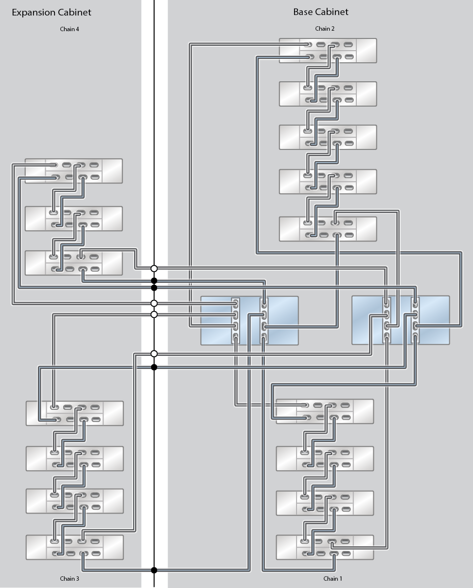
The following diagrams illustrate how pre-racked systems are cabled, as well as how to expand your system in the future. The legend for each diagram is as follows:
-
A hollow circle indicates the cable connection to the top IOM (IOM 1).
-
A solid circle indicates the cable connection to the bottom IOM (IOM 0).
Figure 658 ZS7-2 MR Racked System Capacity Configuration: 11 DE3-24C Disk Shelves
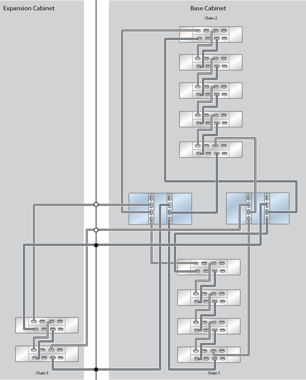
Figure 659 ZS7-2 MR Racked System Capacity Configuration: 13 DE3-24C Disk Shelves
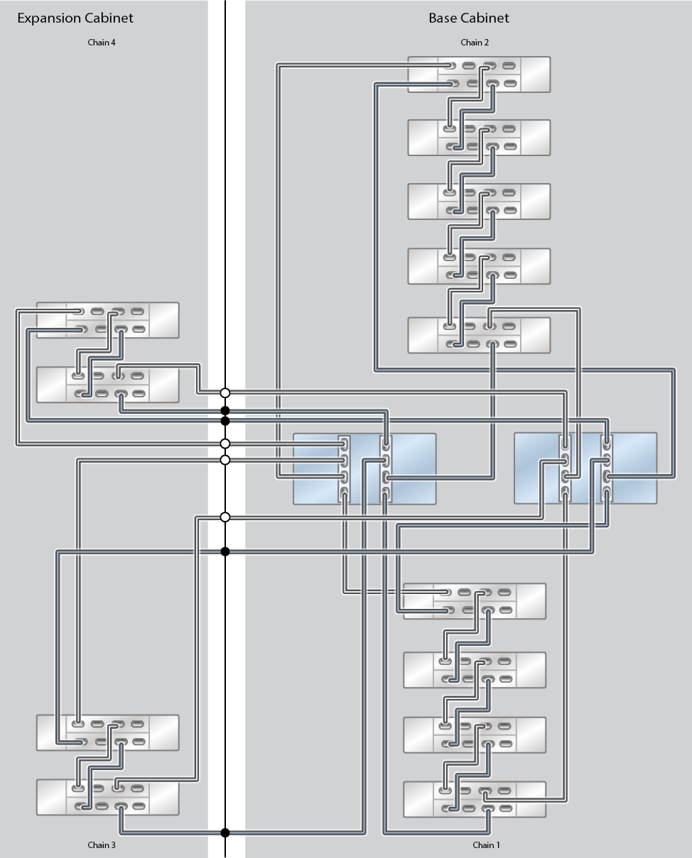
Figure 660 ZS7-2 MR Racked System Capacity Configuration: 14 DE3-24C Disk Shelves (Half Rack)
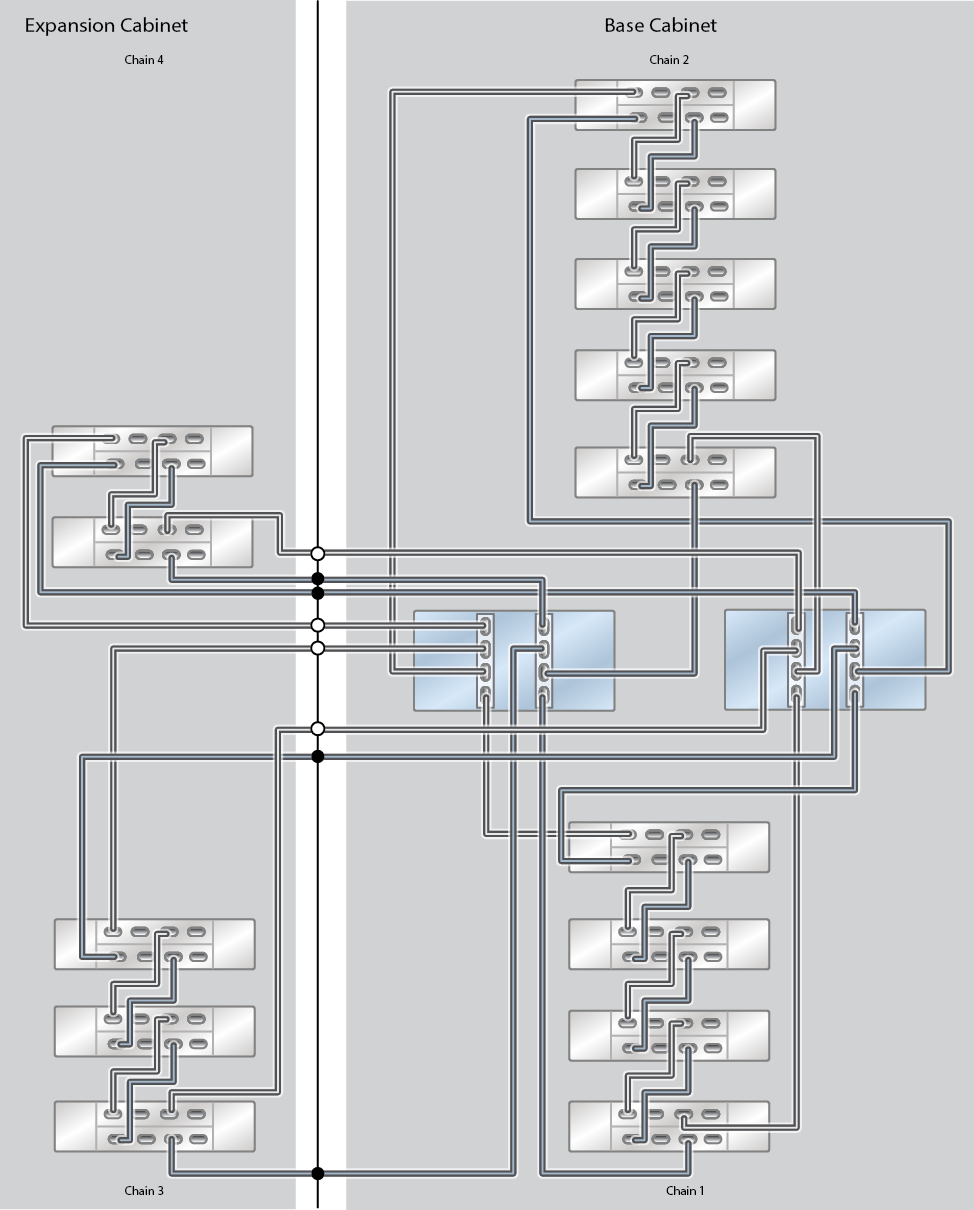
Figure 661 ZS7-2 MR Racked System Capacity Configuration: 15 DE3-24C Disk Shelves
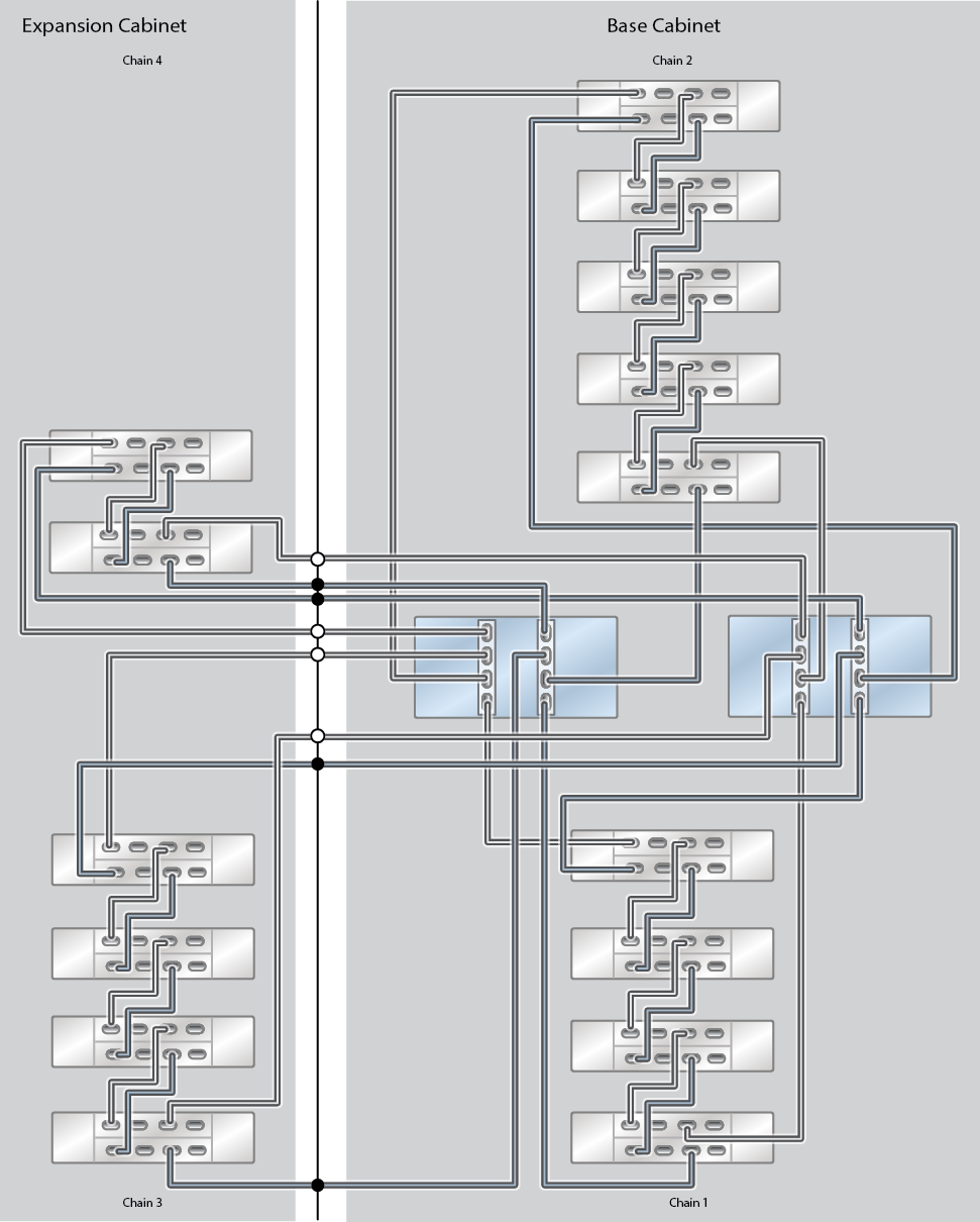
Figure 662 ZS7-2 MR Racked System Capacity Configuration: 16 DE3-24C Disk Shelves
