
The Oracle Private Cloud Appliance controller software allows you to add custom networks at the appliance level. This means that certain hardware components require configuration changes to enable the additional connectivity. The new networks are then configured automatically in your Oracle VM environment, where they can be used for isolating and optimizing network traffic beyond the capabilities of the default network configuration. All custom networks, both internal and public, are VLAN-capable.
Do not modify the network configuration while upgrade operations are running. No management operations are supported during upgrade, as these may lead to configuration inconsistencies and significant repair downtime.
Custom networks must never be deleted in Oracle VM Manager. Doing so would leave the environment in an error state that is extremely difficult to repair. To avoid downtime and data loss, always perform custom network operations in the Oracle Private Cloud Appliance CLI.
The following network limitations apply:
The maximum number of custom external networks is 7 per tenant group or per compute node.
The maximum number of custom internal networks is 3 per tenant group or per compute node.
The maximum number of VLANs is 256 per tenant group or per compute node.
Only one host network can be assigned per tenant group or per compute node.
When configuring custom networks, make sure that no provisioning operations or virtual machine environment modifications take place. This might lock Oracle VM resources and cause your Oracle Private Cloud Appliance CLI commands to fail.
Creating custom networks requires use of the CLI. The administrator chooses between three types: a network internal to the appliance, a network with external connectivity, or a host network. Custom networks appear automatically in Oracle VM Manager. The internal and external networks take the virtual machine network role, while a host network may have the virtual machine and storage network roles.
The host network is a particular type of external network: its configuration contains additional parameters for subnet and routing. The servers connected to it also receive an IP address in that subnet, and consequently can connect to an external network device. The host network is particularly useful for direct access to storage devices.
Network Architecture Differences
Oracle Private Cloud Appliance exists in two different types of network architecture. One is built around a physical InfiniBand fabric; the other relies on physical high speed Ethernet connectivity. While the two implementations offer practically the same functionality, the configuration of custom networks is different due to the type of network hardware.
This section is split up by network architecture to avoid confusion. Refer to the subsection that applies to your appliance.
This section describes how to configure custom networks on a system with an Ethernet-based network architecture.
For all networks with external connectivity, the spine Cisco Nexus 9336C-FX2 Switch ports must be specified so that these are reconfigured to route the external traffic. These ports must be cabled to create the physical uplink to the next-level switches in the data center. For detailed information, refer to Appliance Uplink Configuration in the Oracle Private Cloud Appliance Installation Guide.
Creating a Custom Network on an Ethernet-based System
Using SSH and an account with superuser privileges, log into the active management node.
NoteThe default
rootpassword is Welcome1. For security reasons, you must set a new password at your earliest convenience.# ssh root@10.100.1.101 root@10.100.1.101's password: root@ovcamn05r1 ~]#
Launch the Oracle Private Cloud Appliance command line interface.
# pca-admin
Welcome to PCA! Release: 2.4.2
PCA>
If your custom network requires public connectivity, you need to use one or more spine switch ports. Verify the number of ports available and carefully plan your network customizations accordingly. The following example shows how to retrieve that information from your system:
PCA> list network-port

Port      Switch          Type                   State           Networks
----      ------          ----                   -----           --------
1:1       ovcasw22r1      10G                    down            None
1:2       ovcasw22r1      10G                    down            None
1:3       ovcasw22r1      10G                    down            None
1:4       ovcasw22r1      10G                    down            None
2         ovcasw22r1      40G                    up              None
3         ovcasw22r1      auto-speed             down            None
4         ovcasw22r1      auto-speed             down            None
5:1       ovcasw22r1      10G                    up              default_external
5:2       ovcasw22r1      10G                    down            default_external
5:3       ovcasw22r1      10G                    down            None
5:4       ovcasw22r1      10G                    down            None
1:1       ovcasw23r1      10G                    down            None
1:2       ovcasw23r1      10G                    down            None
1:3       ovcasw23r1      10G                    down            None
1:4       ovcasw23r1      10G                    down            None
2         ovcasw23r1      40G                    up              None
3         ovcasw23r1      auto-speed             down            None
4         ovcasw23r1      auto-speed             down            None
5:1       ovcasw23r1      10G                    up              default_external
5:2       ovcasw23r1      10G                    down            default_external
5:3       ovcasw23r1      10G                    down            None
5:4       ovcasw23r1      10G                    down            None
-----------------
22 rows displayed

Status: Success
For a custom network with external connectivity, configure an uplink port group with the uplink ports you wish to use for this traffic. Select the appropriate breakout mode
PCA> create uplink-port-group
MyUplinkPortGroup'1:1 1:2' 10g-4x Status: SuccessNoteThe port arguments are specified as
'x:y'wherexis the switch port number andyis the number of the breakout port, in case a splitter cable is attached to the switch port. The example above shows how to retrieve that information.You must set the breakout mode of the uplink port group. When a 4-way breakout cable is used, all four ports must be set to either 10Gbit or 25Gbit. When no breakout cable is used, the port speed for the uplink port group should be either 100Gbit or 40Gbit, depending on connectivity requirements. See Section 4.2.9, “create uplink-port-group” for command details.
Network ports can not be part of more than one network configuration.
Create a new network and select one of these types:
rack_internal_networkexternal_networkhost_network
Use the following syntax:
For an internal-only network, specify a network name.
PCA> create network
MyInternalNetworkrack_internal_network Status: SuccessFor an external network, specify a network name and the spine switch port group to be configured for external traffic.
PCA> create network
MyPublicNetworkexternal_networkMyUplinkPortGroupStatus: SuccessFor a host network, specify a network name, the spine switch ports to be configured for external traffic, the subnet, and optionally the routing configuration.
PCA> create network
MyHostNetworkhost_networkMyUplinkPortGroup\ 10.10.10 255.255.255.0 10.1.20.0/24 10.10.10.250 Status: SuccessNoteIn this example the additional network and routing arguments for the host network are specified as follows, separated by spaces:
10.10.10= subnet prefix255.255.255.0= netmask10.1.20.0/24= route destination (as subnet or IPv4 address)10.10.10.250= route gateway
The subnet prefix and netmask are used to assign IP addresses to servers joining the network. The optional route gateway and destination parameters are used to configure a static route in the server's routing table. The route destination is a single IP address by default, so you must specify a netmask if traffic could be intended for different IP addresses in a subnet.
When you define a host network, it is possible to enter invalid or contradictory values for the Prefix, Netmask and Route_Destination parameters. For example, when you enter a prefix with "0" as the first octet, the system attempts to configure IP addresses on compute node Ethernet interfaces starting with 0. Also, when the netmask part of the route destination you enter is invalid, the network is still created, even though an exception occurs. When such a poorly configured network is in an invalid state, it cannot be reconfigured or deleted with standard commands. If an invalid network configuration is applied, use the
--forceoption to delete the network.Details of the create network command arguments are provided in Section 4.2.7, “create network” in the CLI reference chapter.
CautionNetwork and routing parameters of a host network cannot be modified. To change these settings, delete the custom network and re-create it with updated settings.
Connect the required servers to the new custom network. You must provide the network name and the names of the servers to connect.
PCA> add network
MyPublicNetworkovcacn07r1Status: Success PCA> add networkMyPublicNetworkovcacn08r1Status: Success PCA> add networkMyPublicNetworkovcacn09r1Status: SuccessVerify the configuration of the new custom network.
PCA> show network
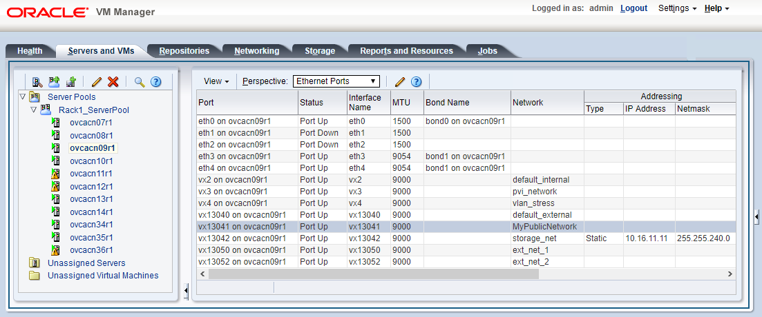
MyPublicNetwork---------------------------------------- Network_Name MyPublicNetwork Trunkmode None Description None Ports ['1:1', '1:2'] vNICs None Status ready Network_Type external_network Compute_Nodes ovcacn07r1, ovcacn08r1, ovcacn09r1 Prefix None Netmask None Route Destination None Route Gateway None ---------------------------------------- Status: SuccessAs a result of these commands, a VxLAN interface is configured on each of the servers to connect them to the new custom network. These configuration changes are reflected in the Networking tab and the Servers and VMs tab in Oracle VM Manager.
NoteIf the custom network is a host network, the server is assigned an IP address based on the prefix and netmask parameters of the network configuration, and the final octet of the server's internal management IP address.
For example, if the compute node with internal IP address 192.168.4.9 were connected to the host network used for illustration purposes in this procedure, it would receive the address 10.10.10.9 in the host network.
Figure 2.7 shows a custom network named MyPublicNetwork, which is VLAN-capable and uses the compute node's
vx13041interface.To disconnect servers from the custom network use the remove network command.
WarningBefore removing the network connection of a server, make sure that no virtual machines are relying on this network.
When a server is no longer connected to a custom network, make sure that its port configuration is cleaned up in Oracle VM.
PCA> remove network
MyPublicNetworkovcacn09r1************************************************************ WARNING !!! THIS IS A DESTRUCTIVE OPERATION. ************************************************************ Are you sure [y/N]:y Status: Success
This section describes how to configure custom networks on a system with an InfiniBand-based network architecture.
For all networks with external connectivity the Fabric Interconnect I/O ports must be specified so that these are reconfigured to route the external traffic. These ports must be cabled to create the physical uplink to the next-level switches in the data center.
Creating a Custom Network on an InfiniBand-based System
Using SSH and an account with superuser privileges, log into the active management node.
NoteThe default
rootpassword is Welcome1. For security reasons, you must set a new password at your earliest convenience.# ssh root@10.100.1.101 root@10.100.1.101's password: root@ovcamn05r1 ~]#
Launch the Oracle Private Cloud Appliance command line interface.
# pca-admin
Welcome to PCA! Release: 2.4.2
PCA>
If your custom network requires public connectivity, you need to use one or more Fabric Interconnect ports. Verify the number of I/O modules and ports available and carefully plan your network customizations accordingly. The following example shows how to retrieve that information from your system:
PCA> list network-card --sorted-by Director

Slot   Director        Type                              State      Number_Of_Ports
----   --------        ----                              -----      ---------------
     3 ovcasw15r1      sanFc2Port8GbLrCardEthIb          up             2
    18 ovcasw15r1      sanFc2Port8GbLrCardEthIb          up             2
    16 ovcasw15r1      nwEthernet4Port10GbCardEthIb      up             4
     5 ovcasw15r1      nwEthernet4Port10GbCardEthIb      up             4
    17 ovcasw15r1      nwEthernet4Port10GbCardEthIb      up             4
     4 ovcasw15r1      nwEthernet4Port10GbCardEthIb      up             4
    16 ovcasw22r1      nwEthernet4Port10GbCardEthIb      up             4
     5 ovcasw22r1      nwEthernet4Port10GbCardEthIb      up             4
    18 ovcasw22r1      sanFc2Port8GbLrCardEthIb          up             2
    17 ovcasw22r1      nwEthernet4Port10GbCardEthIb      up             4
     4 ovcasw22r1      nwEthernet4Port10GbCardEthIb      up             4
     3 ovcasw22r1      sanFc2Port8GbLrCardEthIb          up             2
-----------------
12 rows displayed

Status: Success
PCA> list network-port --filter-column Type --filter nwEthernet* --sorted-by State

Port      Director        Type                   State      Networks
----      --------        ----                   -----      --------
4:4       ovcasw15r1      nwEthernet10GbPort     down       None
4:3       ovcasw15r1      nwEthernet10GbPort     down       None
4:2       ovcasw15r1      nwEthernet10GbPort     down       None
5:4       ovcasw15r1      nwEthernet10GbPort     down       None
5:3       ovcasw15r1      nwEthernet10GbPort     down       None
5:2       ovcasw15r1      nwEthernet10GbPort     down       None
10:4      ovcasw15r1      nwEthernet10GbPort     down       None
10:3      ovcasw15r1      nwEthernet10GbPort     down       None
10:2      ovcasw15r1      nwEthernet10GbPort     down       None
10:1      ovcasw15r1      nwEthernet10GbPort     down       None
11:4      ovcasw15r1      nwEthernet10GbPort     down       None
11:3      ovcasw15r1      nwEthernet10GbPort     down       None
11:2      ovcasw15r1      nwEthernet10GbPort     down       None
11:1      ovcasw15r1      nwEthernet10GbPort     down       None
4:4       ovcasw22r1      nwEthernet10GbPort     down       None
4:3       ovcasw22r1      nwEthernet10GbPort     down       None
4:2       ovcasw22r1      nwEthernet10GbPort     down       None
5:4       ovcasw22r1      nwEthernet10GbPort     down       None
5:3       ovcasw22r1      nwEthernet10GbPort     down       None
5:2       ovcasw22r1      nwEthernet10GbPort     down       None
10:4      ovcasw22r1      nwEthernet10GbPort     down       None
10:3      ovcasw22r1      nwEthernet10GbPort     down       None
10:1      ovcasw22r1      nwEthernet10GbPort     down       None
11:3      ovcasw22r1      nwEthernet10GbPort     down       None
11:2      ovcasw22r1      nwEthernet10GbPort     down       None
11:1      ovcasw22r1      nwEthernet10GbPort     down       None
4:1       ovcasw15r1      nwEthernet10GbPort     up         mgmt_public_eth, vm_public_vlan
5:1       ovcasw15r1      nwEthernet10GbPort     up         mgmt_public_eth, vm_public_vlan
4:1       ovcasw22r1      nwEthernet10GbPort     up         mgmt_public_eth, vm_public_vlan
5:1       ovcasw22r1      nwEthernet10GbPort     up         mgmt_public_eth, vm_public_vlan
10:2      ovcasw22r1      nwEthernet10GbPort     up         None
11:4      ovcasw22r1      nwEthernet10GbPort     up         None
-----------------
32 rows displayed

Status: Success
Create a new network and select one of these types:
rack_internal_networkexternal_networkhost_network
Use the following syntax:
For an internal-only network, specify a network name.
PCA> create network
MyInternalNetworkrack_internal_network Status: SuccessFor an external network, specify a network name and the Fabric Interconnect port(s) to be configured for external traffic.
PCA> create network
MyPublicNetworkexternal_network '4:2 5:2' Status: SuccessNoteThe port arguments are specified as
'x:y'wherexis the I/O module slot number andyis the number of the port on that module. The example above shows how to retrieve that information.I/O ports can not be part of more than one network configuration.
If, instead of using the CLI interactive mode, you create a network in a single CLI command from the Oracle Linux prompt, you must escape the quotation marks to prevent bash from interpreting them. Add a backslash character before each quotation mark:
# pca-admin create network
MyPublicNetworkexternal_network \'4:2 5:2\'For a host network, specify a network name, the Fabric Interconnect ports to be configured for external traffic, the subnet, and optionally the routing configuration.
PCA> create network
MyHostNetworkhost_network '10:1 11:1' \ 10.10.10 255.255.255.0 10.1.20.0/24 10.10.10.250 Status: SuccessNoteIn this example the additional network and routing arguments for the host network are specified as follows, separated by spaces:
10.10.10= subnet prefix255.255.255.0= netmask10.1.20.0/24= route destination (as subnet or IPv4 address)10.10.10.250= route gateway
The subnet prefix and netmask are used to assign IP addresses to servers joining the network. The optional route gateway and destination parameters are used to configure a static route in the server's routing table. The route destination is a single IP address by default, so you must specify a netmask if traffic could be intended for different IP addresses in a subnet.
When you define a host network, it is possible to enter invalid or contradictory values for the Prefix, Netmask and Route_Destination parameters. For example, when you enter a prefix with "0" as the first octet, the system attempts to configure IP addresses on compute node Ethernet interfaces starting with 0. Also, when the netmask part of the route destination you enter is invalid, the network is still created, even though an exception occurs. When such a poorly configured network is in an invalid state, it cannot be reconfigured or deleted with standard commands. If an invalid network configuration is applied, use the
--forceoption to delete the network.Details of the create network command arguments are provided in Section 4.2.7, “create network” in the CLI reference chapter.
CautionNetwork and routing parameters of a host network cannot be modified. To change these settings, delete the custom network and re-create it with updated settings.
Connect the required servers to the new custom network. You must provide the network name and the names of the servers to connect.
PCA> add network
MyPublicNetworkovcacn07r1Status: Success PCA> add networkMyPublicNetworkovcacn08r1Status: Success PCA> add networkMyPublicNetworkovcacn09r1Status: SuccessVerify the configuration of the new custom network.
PCA> show network
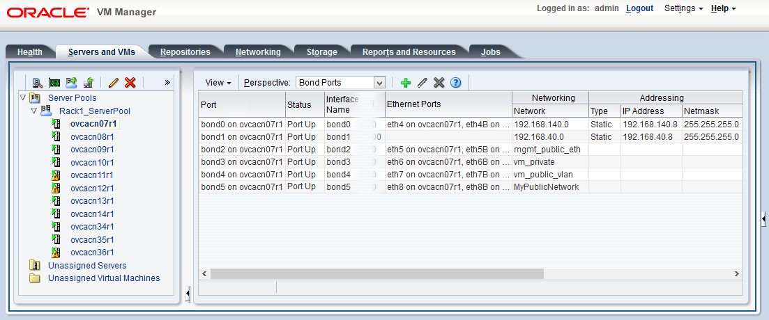
MyPublicNetwork---------------------------------------- Network_Name MyPublicNetwork Trunkmode True Description User defined network Ports ['4:2', '5:2'] vNICs ovcacn09r1-eth8, ovcacn07r1-eth8, ovcacn08r1-eth8 Status ready Network_Type external_network Compute_Nodes ovcacn07r1, ovcacn08r1, ovcacn09r1 Prefix None Netmask None Route Destination None Route Gateway None ---------------------------------------- Status: SuccessAs a result of these commands, a bond of two new vNICs is configured on each of the servers to connect them to the new custom network. These configuration changes are reflected in the Networking tab and the Servers and VMs tab in Oracle VM Manager.
NoteIf the custom network is a host network, the server is assigned an IP address based on the prefix and netmask parameters of the network configuration, and the final octet of the server's internal management IP address.
For example, if the compute node with internal IP address 192.168.4.9 were connected to the host network used for illustration purposes in this procedure, it would receive the address 10.10.10.9 in the host network.
Figure 2.8 shows a custom network named MyPublicNetwork, which is VLAN-enabled and uses the compute node's
bond5interface consisting of Ethernet ports (vNICs)eth8andeth8B.To disconnect servers from the custom network use the remove network command.
WarningBefore removing the network connection of a server, make sure that no virtual machines are relying on this network.
When a server is no longer connected to a custom network, make sure that its port configuration is cleaned up in Oracle VM.
PCA> remove network
MyPublicNetworkovcacn09r1************************************************************ WARNING !!! THIS IS A DESTRUCTIVE OPERATION. ************************************************************ Are you sure [y/N]:y Status: Success
This section describes how to delete custom networks. The procedure is the same for systems with an Ethernet-based and InfiniBand-based network architecture.
Deleting a Custom Network
Before deleting a custom network, make sure that all servers have been disconnected from it first.
Using SSH and an account with superuser privileges, log into the active management node.
NoteThe default
rootpassword is Welcome1. For security reasons, you must set a new password at your earliest convenience.# ssh root@10.100.1.101 root@10.100.1.101's password: root@ovcamn05r1 ~]#
Launch the Oracle Private Cloud Appliance command line interface.
# pca-admin
Welcome to PCA! Release: 2.4.2
PCA>
Verify that all servers have been disconnected from the custom network. No vNICs or nodes should appear in the network configuration.
CautionRelated configuration changes in Oracle VM must be cleaned up as well.
NoteThe command output sample below shows a public network configuration on an Ethernet-based system. The configuration of a public network on an InfiniBand-based system looks slightly different.
PCA> show network MyPublicNetwork

----------------------------------------
Network_Name         MyPublicNetwork
Trunkmode            None
Description          None
Ports                ['1:1', '1:2']
vNICs                None
Status               ready
Network_Type         external_network
Compute_Nodes        None
Prefix               None
Netmask              None
Route_Destination    None
Route_Gateway        None
----------------------------------------
Delete the custom network.
PCA> delete network
MyPublicNetwork************************************************************ WARNING !!! THIS IS A DESTRUCTIVE OPERATION. ************************************************************ Are you sure [y/N]:y Status: SuccessCautionIf a custom network is left in an invalid or error state, and the delete command fails, you may use the
--forceoption and retry.