
The Network Environment window is used to configure networking and service information for the management nodes. For this purpose, you should reserve three IP addresses in the public (data center) network: one for each management node, and one to be used as virtual IP address by both management nodes. The virtual IP address provides access to the Dashboard once the software initialization is complete.
To avoid network interference and conflicts, you must ensure that the data center network does not overlap with any of the infrastructure subnets of the Oracle Private Cloud Appliance default configuration. These are the subnets and VLANs you should keep clear:
Subnets:
192.168.4.0/24 – internal machine administration network: connects ILOMs and physical hosts
192.168.140.0/24 – internal Oracle VM management network: connects Oracle VM Manager, Oracle VM Server and Oracle VM Agents (applies only to the InfiniBand-based architecture)
192.168.32.0/21 – internal management network: traffic between management and compute nodes
192.168.64.0/21 – underlay network for east/west traffic within the appliance environment
192.168.72.0/21 – underlay network for north/south traffic, enabling external connectivity
192.168.40.0/21 – storage network: traffic between the servers and the ZFS storage appliance
Each /21 subnet comprises the IP ranges of
eight /24 subnets or over 2000 IP addresses.
For example: 192.168.32.0/21 corresponds with
all IP addresses from 192.168.32.1 to
192.168.39.255.
VLANs:
1 – the Cisco default VLAN
3040 – the default service VLAN
3041-3072 – a range of 31 VLANs reserved for customer VM and host networks
3073-3099 – a range reserved for system-level connectivity
NoteVLANs 3090-3093 are already in use for tagged traffic over the
/21subnets listed above.3968-4095 – a range reserved for Cisco internal device allocation
The Network Environment window is divided into three tabs: Management Nodes, Data Center Network, and DNS. Each tab is shown in this section, along with a description of the available configuration fields.
You can undo the changes you made in any of the tabs by clicking the Reset button. To confirm the configuration changes you made, enter the Dashboard Admin user password in the applicable field at the bottom of the window, and click Apply Changes.
When you click Apply Changes, the configuration settings in all three tabs are applied. Make sure that all required fields in all tabs contain valid information before you proceed.
Figure 2.4 shows the Management Nodes tab. The following fields are available for configuration:
Management Node 1:
IP Address: Specify an IP address within your datacenter network that can be used to directly access this management node.
Host Name: Specify the host name for the first management node system.
Management Node 2:
IP Address: Specify an IP address within your datacenter network that can be used to directly access this management node.
Host Name: Specify the host name for the second management node system.
Management Virtual IP Address: Specify the shared Virtual IP address that is used to always access the active management node. This IP address must be in the same subnet as the IP addresses that you have specified for each management node.
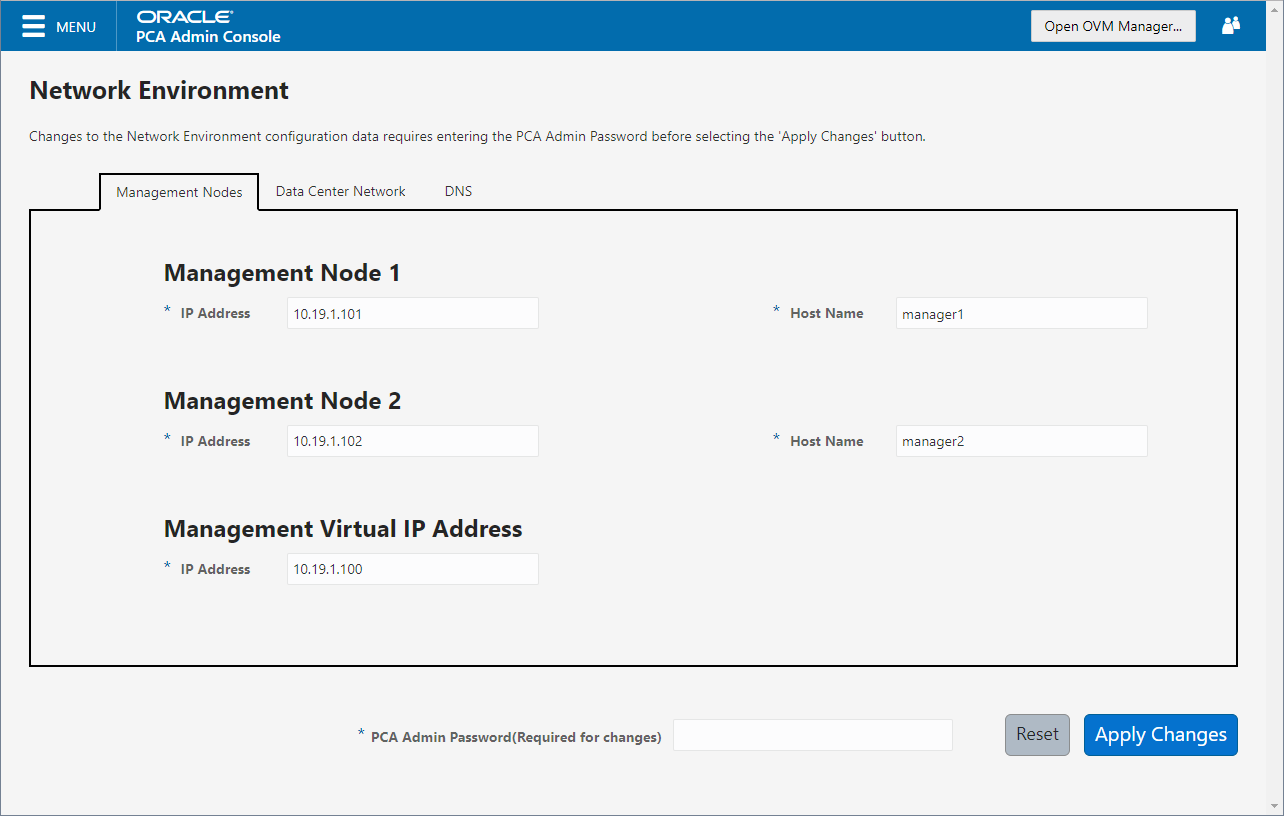
Figure 2.5 shows the Data Center Network tab. The following fields are available for configuration:
Management Network VLAN: The default configuration does not assume that your management network exists on a VLAN. If you have configured a VLAN on your switch for the management network, you should toggle the slider to the active setting and then specify the VLAN ID in the provided field.
CautionFor systems with Ethernet-based network architecture, a management VLAN requires additional configuration steps.
When a VLAN is used for the management network, and VM traffic must be enabled over the same network, you must manually configure a VLAN interface on the vx13040 interfaces of the necessary compute nodes to connect them to the VLAN with the ID in question. For instructions to create a VLAN interface on a compute node, refer to the Create a VLAN section in the Oracle VM documentation.
Domain Name: Specify the data center domain that the management nodes belong to.
Netmask: Specify the netmask for the network that the Virtual IP address and management node IP addresses belong to.
Default Gateway: Specify the default gateway for the network that the Virtual IP address and management node IP addresses belong to.
NTP: Specify the NTP server that the management nodes and other appliance components must use to synchronize their clocks to.
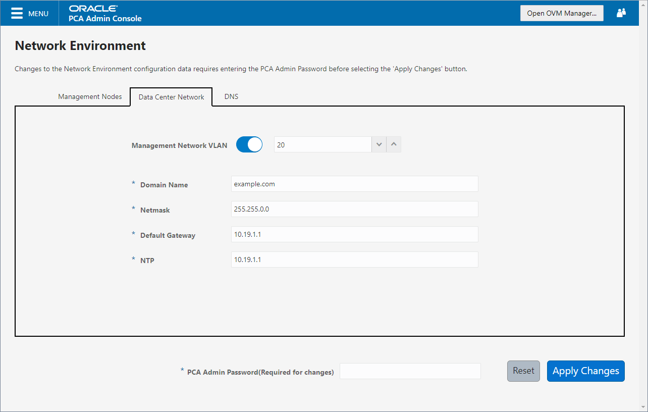
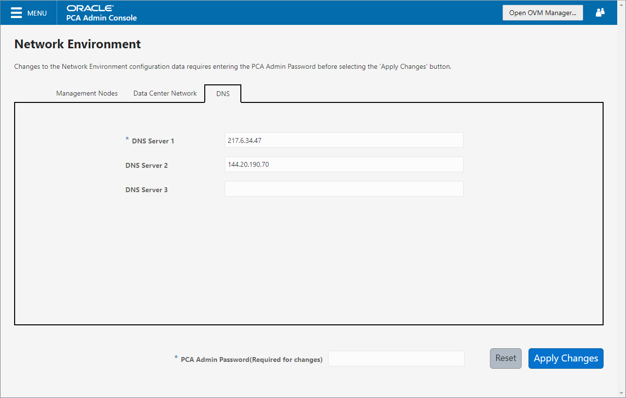
Figure 2.6 shows the Data Center Network tab. The following fields are available for configuration:
DNS Server 1: Specify at least one DNS server that the management nodes can use for domain name resolution.
DNS Server 2: Optionally, specify a second DNS server.
DNS Server 3: Optionally, specify a third DNS server.
You must enter the current Oracle Private Cloud Appliance
Admin account password to make changes to any
of these settings. Clicking the button at the bottom of the page saves the
settings that are currently filled out in all three Network
Environment tabs, and updates the configuration on each of the
management nodes. The ovca services are
restarted in the process, so you are required to log back in to
the Dashboard afterwards.