Internal
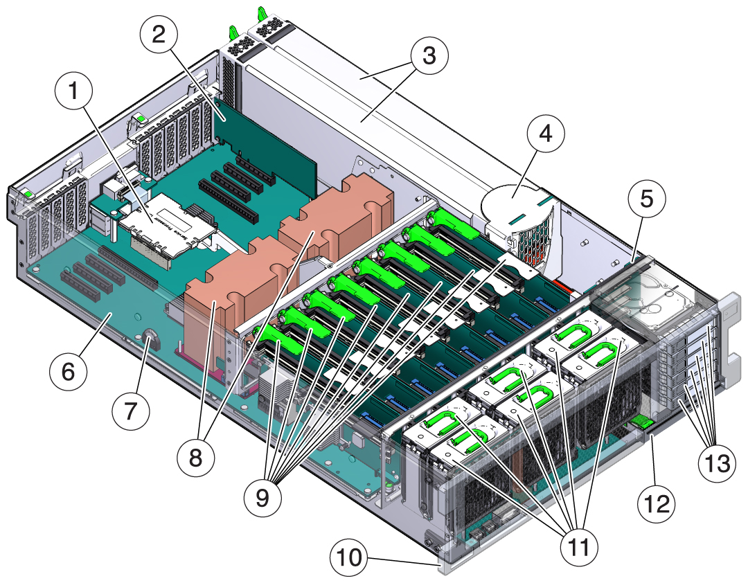
Component Locations
The following figures identify the replaceable component locations
with the top cover removed.

|
|
|
|
1 |
SP board module |
/SYS/MB/SPM |
|
2 |
PCIe card (in slot 1) |
/SYS/MB/PCIE1
/SYS/MB/PCIE2
/SYS/MB/PCIE3
/SYS/MB/PCIE4
/SYS/MB/PCIE5
/SYS/MB/PCIE6
/SYS/MB/PCIE7
/SYS/MB/PCIE8 |
|
3 |
Power supplies |
/SYS/PS0 (outer)
/SYS/PS1 (inner) |
|
4 |
PS backplane and cover |
/SYS/PDB |
|
5 |
Drive backplane |
/SYS/DBP |
|
6 |
Motherboard |
/SYS/MB |
|
7 |
Battery |
/SYS/MB/BAT |
|
8 |
Processor modules and heat sinks (these
are only replaceable by replacing the motherboard) |
/SYS/MB/CM0
/SYS/MB/CM1 |
|
9 |
Memory risers |
/SYS/MB/CM0/CMP/MR0
/SYS/MB/CM0/CMP/MR1
/SYS/MB/CM0/CMP/MR2
/SYS/MB/CM0/CMP/MR3
/SYS/MB/CM1/CMP/MR0
/SYS/MB/CM1/CMP/MR1
/SYS/MB/CM1/CMP/MR2
/SYS/MB/CM1/CMP/MR3 |
|
10 |
Fan board |
/SYS/FANBD |
|
11 |
Fan modules |
As viewed from front of server:
/SYS/FANBD/F0 (left front)
/SYS/FANBD/F1 (center front)
/SYS/FANBD/F2 (right front)
/SYS/FANBD/F3 (left rear)
/SYS/FANBD/F4 (center rear)
/SYS/FANBD/F5 (right rear) |
|
12 |
DVD drive |
/SYS/DBP/DVD
|
|
13 |
Drives |
/SYS/DBP/HDD0 (bottom)
/SYS/DBP/HDD1
/SYS/DBP/HDD2
/SYS/DBP/HDD3
/SYS/DBP/HDD4
/SYS/DBP/HDD5 (top) |
|
|

