Replacing the Centerplane
-
Replace the 24 screws to secure the centerplane to the main chassis.
-
Replace and secure the front chassis to the centerplane.
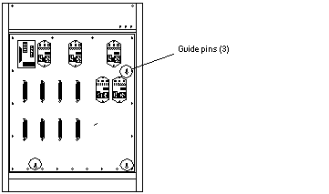
Use the three guide pins to align the front chassis with the centerplane.
Figure E-12 Centerplane Guide Pins

-
Replace the two screws on the top front corners that secure the front chassis to the main chassis. See Figure E-11.
-
Replace the 15 screws on each side that secure the front chassis to the main chassis. See Figure E-11.
-
Connect all the cables to the centerplane.
-
Connect the key switch PWB centerplane cable assembly.
See "Key Switch PWB Centerplane Cable Assembly" for information on connecting this cable.
-
Connect the media tray data and DC power cable assemblies.
See "Media Tray Data and DC Power Cable Assemblies" for information on connecting these cables.
-
-
If present, connect the auxiliary fan tray to the centerplane.
See "Auxiliary Fan Tray Assembly" for information on replacing the auxiliary fan tray.
-
Connect the PCMs to the centerplane.
See Chapter 7, Power Supplies for information on replacing the PCMs.
-
Connect the peripheral power supplies to the centerplane.
See Chapter 7, Power Supplies for information on replacing the peripheral power supplies.
-
Connect all the boards to the centerplane.
See Chapter 3, CPU/Memory+ Boards and Components, Chapter 4, I/O+ Boards and Components, Chapter 5, Clock+ Board, and Chapter 6, Interface Board for information on replacing the boards.
-
Replace all the filler panels.
-
Slide the filler panels toward the centerplane.
Ensure that the arrows in the quarter-turn access slots point to the unlocked position.
The filler panel should insert and seat smoothly. If it binds, remove it, and inspect the slot for any obvious obstructions.
-
Use a Phillips #1 screwdriver to turn the arrows in the quarter-turn access slots to the locked position. See Figure E-2.
-
-
Replace all the disk drives.
See Chapter 8, Internal SCSI and FC-AL Devices for information on replacing the disk drives.
-
Replace the fan tray assembly.
See "Fan Tray Assembly" for information on replacing the fan tray assembly.
-
Replace the panels covering the front of the chassis.
Complete the steps in Appendix E, Non-Chassis Field Replaceable Units (FRUs).
- © 2010, Oracle Corporation and/or its affiliates
