Using the HL7 JCA Adapter
The following document provides information on basic operations for the HL7 JCA Adapter.
What You Need to Know
What You Need to Do
Installing the HL7 JCA Adapter
The design-time and runtime files that constitute the HL7 JCA Adapter are supplied in the Java CAPS Adapter Pack.
Design-Time Files (*.nbm) Under .../AdapterPack/NetBeansModules/
-
com-sun-soabi-adapters-hl7-jca.nbm
-
com-sun-soabi-adapters-hl7-uitool.nbm
Design-time *.nbm files are installed using the NetBeans IDE, menu option Tools -> Plugins.
Runtime File (Global RAR) Under .../AdapterPack/Runtime/adapters/
-
sun-hl7-adapter.rar
Runtime RAR files are installed using the GlassFish Admin Console
Note –
Installation may require additional files if there are any dependencies. You will be notified of any required files during installation.
Requirements
To use the Java CAPS 6.2 JCA Adapters you must have an existing GlassFish v2.1 environment, available from Open ESB Downloads.
What You Need To Do
Installing the Design-Time NBM Files for the HL7 JCA Adapter
This section provides step-by-step instructions for installing the design-time files (NetBeans modules) for the HL7 JCA Adapter.
 To Install the NetBeans Modules for the HL7 JCA Adapter
-
Extract the Adapter Pack to your Java CAPS installation directory.
-
In the NetBeans IDE main menu, select Tools -> Plugins.
The Plugins dialog box appears and the list of plugins is initialized.
-
Click the Downloaded tab.
The dialog box lists plugins that have been downloaded but not installed.
-
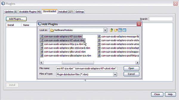
Click the “Add Plugins” button.
The Add Plugins dialog box appears.
-
In the Add Plugins dialog, take the following steps:
-
Navigate to the location of the *.nbm files in the Adapter Pack.
These are by default located in .../NetBeansModules/.
-
If you have not previously done so, open the commonlib folder and install all of the commonlib .nbm files.
-
Back in the NetBeansModules folder, select group-select com-sun-soabi-adapters-message-lib.nbm and the two HL7 NBM files, and click Open.
You may find it easier to simply select all of the NetBeans modules and install them.
If any of the files have already been downloaded, you are prompted to overwrite the existing file(s) or cancel the operation.
-
-
Back in the Plugins dialog, click Install.
-
In the NetBeans Installer wizard, click Next, accept the terms of the license agreement, and then click Install.
-
When the installation ends, choose whether to restart the IDE immediately or later, and then click Finish.
Setting Up the Runtime Environment for the HL7 JCA Adapter
This section provides step-by-step instructions for installing the RAR file for the HL7 JCA Adapter and setting up the GlassFish runtime environment using the Admin Console.
Perform the following steps to set up the runtime environment for the HL7 JCA Adapter:
 To Deploy the Global RAR for
the HL7 JCA Adapter from the Admin Console
-
Start the GlassFish application server.
-
Access Admin Console by pointing your browser at http://localhost:4848
If your application server is running on a remote machine, and/or uses a port other than 4848 for administration, make the appropriate changes to the URL.
-
Log in to Admin Console.
-
In the Common Tasks pane on the left side, expand Applications -> Connector Modules.
If “sun-hl7-adapter” appears in the list, the RAR has already been installed.
-
In the “Deploy Enterprise Applications/Modules” pane, do the following and then click OK.
-
In the “Edit Resource Adapter Properties” pane, you can optionally supply or edit properties. Then click Finish.
Result: Once you have deployed the global RAR onto the application server, you will be able to see it in the NetBeans IDE under Servers -> GlassFish V2 -> Applications -> Connector Module:
 To Add a Connector Connection
Pool for the HL7 JCA Adapter
You will use Admin Console Resources -> Connectors -> Connector Connection Pools to add a new pool for sun-hl7-adapter.
-
If you have not already done so, start GlassFish and log in to Admin Console.
-
In the Common Tasks pane on the left, expand Resources -> Connectors -> Connector Connection Pools.
-
In the Connector Connection Pools pane, click the “New” button.
-
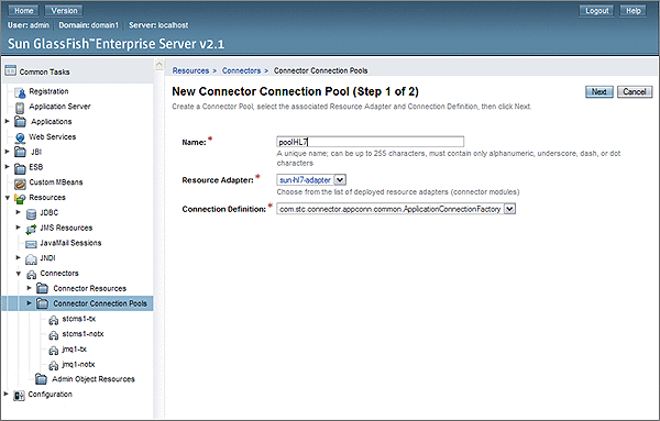
In step 1 of the wizard, supply the following information and then click Next.
-
Name: Supply a name for the HL7 pool, such as poolHL7.
-
Resource Adapter: Choose sun-hl7–adapter.
-
Connection Definition: Retain the default provided when you choose the adapter.
-
-
In step 2 of the wizard, retain or change the settings provided and then click Finish.
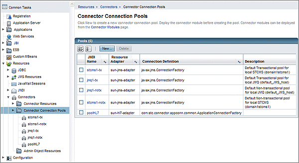
Result: The new pool appears in the tree. You can see it in the NetBeans IDE under Servers -> GlassFish V2 -> Resources -> Connectors -> Connector Connection Pools:
 To Add a Connector Resource for
the HL7 JCA Adapter
-
If you have not already done so, start GlassFish and log in to Admin Console.
-
In the Common Tasks pane on the left, expand Resources -> Connectors -> Connector Resources.
-
In the Connector Resources pane on the right, click the “New” button.
-
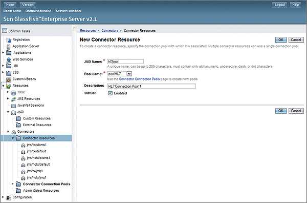
Supply the following information and then click OK.
-
JNDI Name: Supply a name, such as hl7pool by which applications will reference the HL7 pool.
-
Pool Name: Choose a connector connection pool for HL7, such as the one created in the previous procedure.
-
Description: Optionally, supply a meaningful description of this particular JNDI resource.
Result: The new resource appears in the tree. You will be able to see it in the NetBeans IDE under Servers -> GlassFish V2 -> Resources -> Connectors -> Connector Resources:
-
Configuring the HL7 JCA Adapter
The runtime properties of an HL7 JCA Adapter pool can be viewed in the NetBeans IDE, but can only be configured using the Admin Console. A subset of these properties can be overridden at the individual component level using the NetBeans IDE. For detailed step-by-step procedures, see:
Related Topics
For a complete list and description of all configuration settings, see:
For instructions on initially installing HL7 JCA Adapters, see:
For instructions on using HL7 JCA Adapters at design-time, see:
Configuring Runtime Properties of a HL7 JCA Adapter Pool
This section provides a step-by-step procedure for using the Admin Console to configure an existing connector pool for the HL7 JCA Adapter.
 To Configure a HL7 JCA Adapter Pool
You will use Admin Console to access the CAPS Connector Connection Pools and select an existing pool.
-
Start GlassFish if it is not already running.
-
Point your browser at http://localhost:4848 to access Admin Console.
If GlassFish is running on a remote host, or if the administration port is other than 4848, make the appropriate changes in the URL.
-
Log in to Admin Console.
-
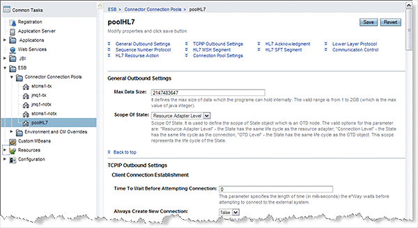
In the Common Tasks pane on the left, expand ESB (or CAPS) -> Connector -> Connector Connection Pools:
-
Click the connector connection pool for HL7 that you want to configure:
-
Make changes as needed to the configuration settings, and then click Save.
For a list and description of the parameters you can set, see Configuration Settings for the HL7 JCA Adapter.
Configuring Design-time Properties of an Individual HL7 JCA Adapter Component
This section provides a step-by-step procedure for using the NetBeans IDE to configure an existing instance of a HL7 JCA Adapter in an EJB project.
 To Configure an HL7 JCA Adapter Instance
Use the NetBeans IDE Projects tab to open the EJB Module project and its Java Collaborations folder, which allows you to edit the configuration properties of an existing HL7 JCA Adapter instance.
-
In the NetBeans IDE, Projects tab, locate the EJB Module project containing the instance you want to configure
-
Open the project's Java Collaborations folder.
-
Right-click the package name and select Edit JCA Activation:
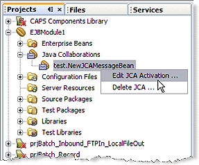
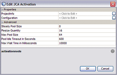
The Edit JCA Activation dialog box appears
-
In the Properties section, click the ellipsis [...] button to the right of “Configuration”:
-
Make changes as needed to the configuration settings, and then click OK.
For a list and description of the parameters you can set, see Configuration Settings for the HL7 JCA Adapter.
Using the HL7 JCA Adapter in an EJB Project
The following provides step-by-step instructions for creating an instance of an HL7 JCA Adapter in an EJB project.
What You Need to Do
Designing an EJB Module to Use HL7 JCA Adapter Code
This section provides step-by-step procedures for creating an EJB Module project and populating it with HL7 JCA Adapter code.
 To Create an EJB Module Project
-
In the NetBeans IDE main menu, click File -> New Project.
The New Project wizard appears.
-
Select the following category and project type and then click Next:
-
Category: Java EE
-
Project: EJB Module
-
-
Provide a project name and location and then click Next.
-
Keep the default values for Server and Java EE Version, and click Finish.
The new project is added to the Projects tree.
 To Add a HL7 JCA Adapter to an EJB
Project
-
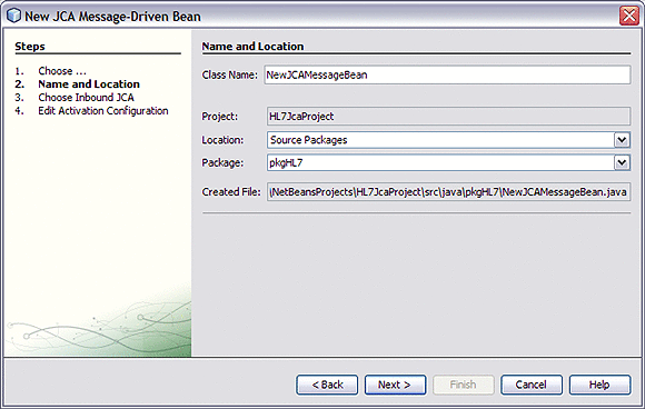
Right-click the EJB Module project and select New -> JCA Message-Driven Bean:
The New JCA Message-Driven Bean wizard appears.
-
Provide a package name and then click Next:
-
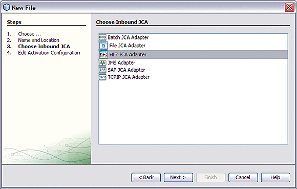
For the Choose Inbound JCA step, select HL7 JCA Adapter and then click Next:
-
In the final step of the wizard, you can optionally edit the instance properties before clicking Finish.
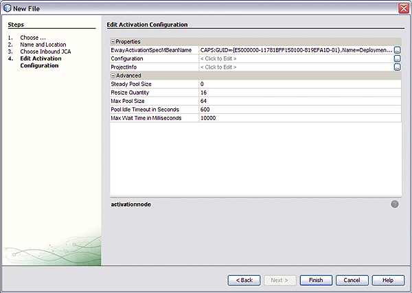
If you click the ellipsis to the right of the Configuration property (as shown above), you can view or edit configuration settings of the HL7 JCA Adapter:
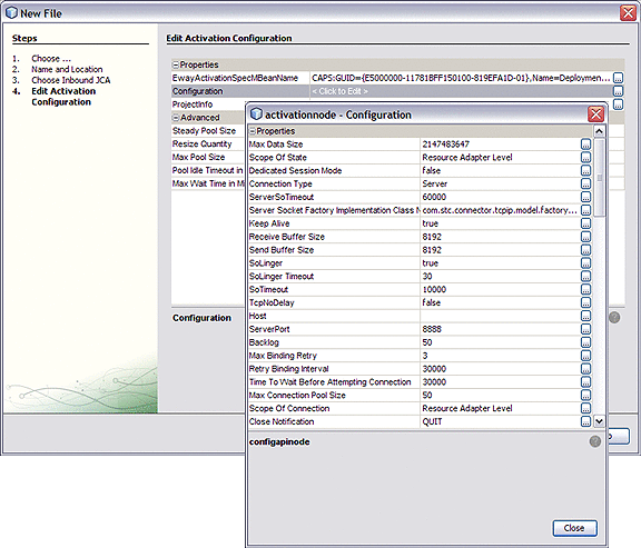
For a complete list and description of configuration properties, see Configuration Settings for the HL7 JCA Adapter.
 To Use HL7-Specific Sample Code
-
In the NetBeans IDE, open the .java file containing the message-driven bean you just created.
-
From the palette, under JCA, drag the HL7 JCA onto the code canvas and drop it between the curly brackets of the receive as shown in the following illustration:
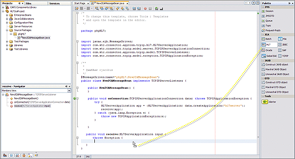
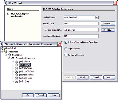
When the HL7 JCA is dropped into the Receive method, the JCA Wizard appears.
-
In the JCA Wizard, provide appropriate values for the HL7 JCA Adapter declaration and then click Finish
Result:HL7 code is added, as shown below. Note that the code in the image below was wrapped for display purposes.
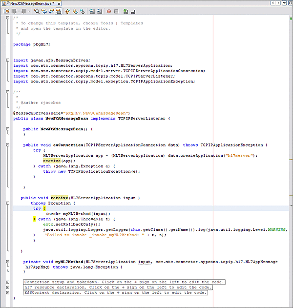
The expanded code appears as follows.
  public void receive(HL7ServerApplication input )
      throws Exception {
       try {
           _invoke_myHL7Method(input);
       } catch (java.lang.Throwable t) {
           ectx.setRollbackOnly();

java.util.logging.Logger.getLogger(this.getClass().getName()).log(java.util.logging.Level.
WARNING, "Failed to invoke _invoke_myHL7Method: " + t, t);
       }
         }

   private void myHL7Method(HL7ServerApplication input, com.stc.connector.appconn.tcpip.
hl7.HL7AppMessage hl7AppMsg) throws java.lang.Exception {
   }

   // <editor-fold defaultstate="collapsed" desc="Connection setup and takedown. Click
on the + sign on the left to edit the code.">
   private void _invoke_myHL7Method(HL7ServerApplication input) throws java.lang.Exception {
       com.stc.connector.appconn.common.ApplicationConnection hl7Connection = null;
       try {
           java.util.Properties hl7Props = new java.util.Properties();
           hl7Props.put("conn-props.collaboration.oid", "placeholder");
           hl7Props.put("conn-props.connection.name", "placeholder");
           hl7Connection = hl7.getConnection(hl7Props);
           com.stc.connector.appconn.tcpip.hl7.HL7ClientApplication hl7OTD = (com.stc.
connector.appconn.tcpip.hl7.HL7ClientApplication) hl7Connection.createApplication("");
           com.stc.connector.appconn.tcpip.hl7.HL7AppMessage hl7AppMsg = hl7OTD.getHL7Message();
           myHL7Method(input, hl7AppMsg);
       } finally {
           try {
               if (hl7Connection != null) {
                   hl7Connection.close();
               }
           } catch (Exception e) {
           }
       }
   } // </editor-fold>
   // <editor-fold defaultstate="collapsed" desc="hl7 resource declaration. Click on the +
sign on the left to edit the code.">
   // comments for inserted variable
   @javax.annotation.Resource(name = "esb/poolHL7", description = "", shareable = false)
   private com.stc.connector.appconn.common.ApplicationConnectionFactory hl7; // </editor-fold>
   // <editor-fold defaultstate="collapsed" desc="EJBContext declaration. Click on the +
sign on the left to edit the code.">
   @javax.annotation.Resource
   private javax.ejb.EJBContext ectx; // </editor-fold>
}
Note –The above code is wrapped for display purposes.
-
Expand each block and edit the code as needed for your implementation.
Configuration Settings for the HL7 JCA Adapter
The following categories of configuration parameters are listed and described:
For step-by-step procedures on configuring the HL7 JCA Adapter, refer to Configuring the HL7 JCA Adapter.
General Outbound Settings
The General Outbound properties specify top-level parameters for the HL7 JCA Adapter.
- Max Data Size
-
Default: 2147483647
Specifies the maximum amount of data that can be held internally. This ranges from 1 to 2147483647 (bytes). The default is 2147483647.
- Scope Of State
-
Specifies the scope of state, which is an OTD node. This scope represents the life cycle of the state.
The choices are:
-
Resource Adapter Level: Specifies that the state has the same lifecycle as the resource adapter.
-
Connection Level: Specifies that the state has the same lifecycle as the connection.
-
OTD Level: Specifies that the state has the same lifecycle as the OTD object.
-
HL7 Outbound Settings — Client Connection Establishment
The Client Connection Establishments settings control the connection when the Connection Type is Client.
- Time To Wait Before Attempting Connection
-
Specifies the length of time (in milliseconds) that the adapter waits before attempting to connect to the external system. The default is 0 (milliseconds); in other words, no wait time.
- Always Create New Connection
-
Specifies whether the eWay always attempts to create a new connection when a connection establishment request is received.
The choices are:
-
True: Attempts to create a new connection without attempting to match an existing connection.
-
False: Attempts to match an existing connection managed by the container.
The default setting is false.
-
- Auto Reconnect Upon Matching Failure
-
Specifies whether to attempt to reconnect automatically when the adapter gets a matching connection from a container, even though this connection might not be valid for various reasons (for example, the external side of the connection is closed/reset due to the external application's logic).
The choices are:
-
True: The adapter discards the invalid matching connection and automatically attempts to reconnect using a new connection.
Specifies that the eWay discards the invalid matching connection and automatically attempts to reconnect using a new connection.
-
False: The adapter does not automatically attempt to reconnect using a new connection: instead, it defers the reconnect control to the user business rules. The user must detect this type of failure and act appropriately
-
- Max Connection Retry
-
Specifies the maximum number of attempts at making a connection with the external HL7 server (host/port) before giving up. The configured default is 3.
- Retry Connection Interval
-
Specifies the number of milliseconds to wait between attempts to connect to the external HL7 server (host/port). The default is 30000; in other words, 30 seconds
HL7 Outbound Settings — Server Port Binding
The Server Port Binding settings control the connection when the Connection Type is Server.
- Max Binding Retry
-
Default: 3
Specifies the maximum number of times the adapter attempts to bind to the specified TCP/IP port on the localhost before giving up. The default is 3.
- Retry Binding Interval
-
Specifies the number of milliseconds to wait between attempts to bind to the specified TCP/IP port on the localhost. The configured default is 30000; in other words, 30 seconds.
TCPIP Outbound Settings
The TCPIP Outbound properties specify general and socket settings (Java Socket Options) for the HL7 JCA Adapter.
- Connection Type
-
Specifies how the eWay establishes the TCP/IP connection.
The choices are:
-
Client: The adapter is in active mode, connecting to an external TCP/IP server (host/port).
-
Server: The adapter is in passive mode, listening on a particular port for an incoming connection request from an external TCP/IP client.
-
- ServerSoTimeout
-
Applies only when Connection Type is set to Server.
Gets or sets the value of the SO_TIMEOUT socket option for the ServerSocket, used for ServerSocket.accept(). A value of 0 is interpreted as an infinite timeout.
To have effect, this option must be enabled prior to entering the blocking operation. When it is set to a nonzero timeout, calling accept() for ServerSocket blocks for only the specified number of milliseconds. If the timeout expires, a java.net.SocketTimeoutException or java.net.InterruptedIOException is thrown, even though the ServerSocket remains valid. The configured default is 60000; in other words, one minute.
- Keep Alive
-
Specifies whether the client's SO_KEEPALIVE option is enabled or disabled. When the option is set for a TCP socket and no data has been exchanged across the socket in either direction for 2 hours, TCP automatically sends a Keep Alive probe to the peer (the actual value is implementation dependent). This probe is a TCP segment to which the peer must respond.
One of three responses is expected:
-
The peer responds with the expected ACK. The application is not notified (since everything is OK). TCP will send another probe following another 2 hours of inactivity.
-
The peer responds with an RST, which tells the local TCP that the peer host has crashed and rebooted. The socket is closed.
-
There is no response from the peer. The socket is closed. The purpose of this option is to detect if the peer host has crashed. This is used for the accepted client Socket.
The Keep Alive value choices are:
-
True: The SO_KEEPALIVE socket option is enabled: After prolonged period of inactivity, a keepalive probe is sent automatically, and the socket is either kept open (if the probe fetches an ACK response) or closed (if the probe fetches a RST response or no response).
-
False: The SO_KEEPALIVE socket option is disabled.
-
- Receive Buffer Size
-
Sets or Gets the value of the SO_RCVBUF option for this Socket. It sets a hint of the size of the underlying buffers used by the platform for incoming network I/O.
When used as Set, this is a suggestion to the kernel from the application about the size of buffers to use for the data to be received over the socket.
When used as Get, this must return the actual size of the buffer used by the platform when receiving data on this socket.
The configured default is 8192 (bytes).
- Send Buffer Size
-
Sets or Gets the value of the SO_SNDBUF option for this Socket. It sets a hint of the size of the underlying buffers used by the platform for outgoing network I/O.
When used as Set, this is a suggestion to the kernel from the application about the size of buffers to use for the data to be sent over the socket.
When used as Get, this must return the actual size of the buffer used by the platform when sending out data on this socket.
The configured default is 8192 (bytes).
- SoLinger
-
Specifies whether the adapter performs a linger-on-close timeout. This option disables/enables immediate return from a close() of a TCP Socket. This parameter is used in conjunction with SoLinger Timeout.
The choices are:
-
True: Enables the SO_LINGER socket option, causing a nonzero SoLinger Timeout value to be applied.
-
False: Disables the SO_LINGER socket option.
-
- SoLinger Timeout
-
Specifies the SoLinger timeout in seconds. This is used in conjunction with the SoLinger parameter.
When SoLinger is set to true (enabled), the SoLinger Timeout value indicates the following:
-
0 (zero) indicates that SoLinger immediately performs a forceful close.
-
A non-zero integer means that calling close() will block, pending the transmission and acknowledgement of all data written to the peer, at which point the socket is closed gracefully. Upon reaching the linger timeout, the socket is closed forcefully with a TCP RST. If the specified timeout value exceeds 65,535 it will be reduced to 65,535.
-
The default is -1 seconds, which indicates that the SoLinger option is disabled (set as false).
The configured default is -1.
-
- SoTimeout
-
Sets/Gets SO_TIMEOUT, in milliseconds. With this option set to a non-zero timeout, a read() call on the InputStream associated with this Socket will block for only this amount of time. If the timeout expires, a java.io.InterruptedIOException (or java.net.SocketTimeoutException) is raised, though the Socket is still valid. The option must be enabled prior to entering the blocking operation to have effect. The timeout must be > 0. A timeout of zero is interpreted as an infinite timeout.
The configured default is 10000; in other words, 10 seconds.
- TcpNoDelay
-
Specifies whether the server's TcpNoDelay option (that is, Nagle's algorithm) is enabled or disabled.
The choices are:
-
True: Indicates that the server allows data packets that are less than the maximum transfer unit (MTU) size to be sent out immediately over the network. A setting of True may improve performance for higher speed networks.
-
False: Indicates that the server does not allow data packets that are less than the MTU size be sent out immediately over the network.
The configured default is False.
-
- Socket Factory Implementation Class Name
-
Specifies the name of the Java class that implements the socket factory. This class is used to create the socket. If you have provided your own socket implementation, enter the name of the Java class that contains this implementation here.
The factory implementation class must implement the following interface: com.stc.connector.tcpip.model.factory.TCPIPSocketFactory
- Host
-
Specifies the hostname or IP address to use for establishing a HL7 connection. Applies only when Connection Type is set to Client. The configured default is localhost.
- Port
-
Default: 8888
Specifies the port number of the TCP/IP destination. If the Connection Type is Server, it indicates the port number on the local host; if the Connection Type is Client, it indicates the port number of the external Host. The port must be between 0 and 65535.
- Backlog
-
Specifies the maximum length of the queue when creating the ServerSocket. The maximum queue length for incoming connection indications (a request to connect) is set to the backlog parameter. If a connection indication arrives when the queue is full, the connection is refused.
HL7 Acknowledgment Settings
The HL7 Acknowledgment settings specify how the application acknowledgment events are handled.
- Acknowledgment Level
-
Specifies whether the external application sends an HL7 application Acknowledgement after successfully receiving a message, or after the message has been successfully committed to the application database.
The options are A and C:
-
A: Application acknowledgment. The acknowledgement is sent when the message is successfully received.
-
C: Commit (accept) acknowledgment. The acknowledgement is sent after the message is successfully and functionally processed by one receiving system.
-
- eGate Sends App Acks
-
Specifies whether the HL7 application acknowledgment sent to the external system is generated by the adapter or forwarded from the ESB.
-
True: Indicates that the ESB receives or creates the HL7 application acknowledgment and sends it to the adapter, which in turn forwards it to the external system.
-
False: Indicates that the adapter creates and sends the HL7 application acknowledgment directly to the external system.
-
- Forward External Acks To eGate
-
Specifies whether the HL7 application acknowledgment is forwarded to the ESB. When an HL7 application acknowledgment is received, it is sometimes necessary to forward the contents of the HL7 application acknowledgment to Java CAPS (as data).
-
True: Indicates that adapter forwards HL7 application acknowledgments from the external system to the ESB for processing.
-
False: Indicates that HL7 application acknowledgments from the external system are not forwarded to the ESB by the adapter.
-
- Timeout For Delayed ACK
-
Specifies the timeout value for delayed ACK in milliseconds. The configured default is 30000 (30 seconds).
Lower Layer Protocol Settings
Provides Lower Layer Protocol (LLP) configuration settings.
- LLP Type
-
Specifies the LLP (Lower Layer Protocol) type.
-
MLLP: Minimal Lower Layer Protocol.
-
HLLP: Hybrid Lower Layer Protocol.
-
MLLP: Minimal Lower Layer Protocol version 2.0.
The options are A and C:
-
- Start Block Character:
-
Specifies the Start Block Character (the first envelope marker character in the HL7 envelope) as a decimal ASCII number. The range is from 1 to 127. Unless there is a conflict, the value should be ASCII VT (decimal 11).
- End Data Character:
-
Specifies the End Data Character (The second to the last envelope marker character in the HL7 envelope) as a decimal ASCII number. The allowed range is 1 to 127. Unless there is a conflict, the value should be ASCII FS (decimal 28).
- End Block Character:
-
Specifies the End Block Character (the last envelope marker character in the HL7 envelope) as a decimal ASCII number. The range is from 1 to 127. To be strictly compliant with the HL7 Standard, this parameter must be set to a carriage return (decimal 13).
- HLLP Checksum Enabled:
-
Specifies whether the HLLP (Hybrid Lower Level Protocol) checksum is enabled or disabled.
-
True: Indicates checksum is enabled.
-
False: Indicates checksum is disabled.
-
- Max Number of Retries:
-
Specifies the maximum number of times the adapter tries to send the message after receiving the MLLP v2.0 Negative Commit Acknowledgement from the peer. The default is 5.
Sequence Number Protocol Settings
Provides sequence number protocol configuration settings. HL7 sequence numbering is used to help prevent duplication of data.
- Sequence Number Enabled
-
Specifies whether Sequence Number Protocol is enabled or disabled. HL7 sequence numbering is used to help prevent duplication of data.
-
True: Indicates that sequence numbering is enabled.
-
False: Indicates that sequence numbering is not enabled.
-
- Sequence Number File Location
-
Specifies the Sequence Number File Location (a local folder name). This is required when the Sequence Number Protocol is Enabled. It is used to store the sequence number files which are used to persist the HL7 Sequence Number. The unique base file name will be generated according to project collaboration information. The default is /temp/hl7outbound/seq
HL7 MSH Segment Settings
Provides the HL7 MSH Header segment configuration settings.
- Field Separator
-
Specifies the separator between the segment ID and the first real field. This value defines the character that is used as a separator for the rest of the message. This is the first field in the HL7 MSH segment (MSH-01).
This is a decimal ASCII number ranging from 1 to 127. The default setting is 124 which is the character '|'.
- Encoding Characters
-
Specifies four encoding characters in the following order:
-
Component separator
-
Repetition separator
-
Escape character
-
Subcomponent separator
The configured default is: ^~\& (ASCII 94, 126, 92, and 38, respectively).
This is the second field in the HL7 MSH segment (MSH-02).
-
- Sending Application
-
Specifies the sending application among other applications within the network enterprise. The network enterprise consists of the applications that participate in the exchange of HL7 messages within the enterprise. This is the third field in the HL7 MSH segment (MSH-03).
- Sending Facility
-
Specifies (further identifies) the sending application among multiple identical instances of the application running on behalf of different organizations. This is the forth field in the HL7 MSH segment (MSH-04).
- Receiving Application
-
Specifies the receiving application among other applications within the network enterprise. The network enterprise consists of the applications that participate in the exchange of HL7 messages within the enterprise. This is the fifth field in the HL7 MSH segment (MSH-05).
- Receiving Facility
-
Specifies (further identifies) the receiving application among multiple identical instances of the application running on behalf of different organizations. This is the sixth field in the HL7 MSH segment (MSH-06).
- Security
-
Specifies the implemented application level security features. This is the eighth field in the HL7 MSH segment (MSH-08).
- Processing ID
-
Specifies the sub-component Processing ID of MSH-11. MSH-11 is used to indicate whether a message is processed as defined in the HL7 Application (level 7) Processing rules.
-
D: Debugging
-
P: Production
-
T: Training
In some cases there may be an additional subcomponent "Processing Mode" following the initial value. The configured default is P.
-
- Version ID
-
Specifies the particular HL7 version to be matched by the receiving system to its own version. This is the 12th field in the HL7 MSH segment (MSH-12).
The HL7 Standard version value as displayed in HL7 Table 0104 - Version ID. The configured default value is 2.5.
- Country Code
-
Specifies a code that indicates the country of origin for the message (see HL7 Table 0399). Used to specify default elements in a message such as currency. This is the 17th field in the HL7 MSH segment (MSH-17).
The Country Code value uses the 3-character (alphabetic) form of ISO 3166. The default value is USA.
- Character Set
-
Specifies the character sets used by the messages (see HL7 Table 0211). If the field is left blank, the character set used is understood to be the 7-bit ASCII set. This is the 18th field in the HL7 MSH segment (MSH-18).
The configured default is 8859/1 (printable 7-bit ASCII character set). See HL7 Table 0211 for available values and descriptions.
- Principal Language Of Message
-
Specifies the principal language of the message. Codes come from ISO 639. This is the 19th field in the HL7 MSH segment (MSH-19). The value is a 2-character ISO 639 alphabetic code.
- Alternate Character Set Handling Scheme
-
Specifies the value for the alternate character set handling scheme to be used when any alternative character sets are used and a special handling scheme is necessary (see HL7 Table 0356). This is the 20th field in the HL7 MSH segment (MSH-20).
Available values include ISO 2022-1994, 2.3, or (blank). Leaving the field blank indicates that no character set switching will occur.
- Conformance Statement ID
-
The Conformance Statement ID (Message Profile Identifier in V2.5) is a unique identifier that applies to a query's Conformance Statement, or as a Message Profile Identifier, asserts constancy with a message profile (grammar, syntax, usage, and so forth). This is the 21st field in the HL7 MSH segment (MSH-21).
The required value is an HL7 Conformance Statement ID value or leave blank.
- Validate MSH
-
Specifies whether to validate the MSH segment of the data message (for inbound) and the MSH segment of the ACK (for outbound).
The required value is True or False. True indicates that the Collaboration validates the MSH segment. The configured default is True.
Note that this property does not affect structural validation of the whole HL7 message itself. Structural validation is always performed.
HL7 SFT Segment Settings
Provides the HL7 SFT Segment configuration settings. The SFT segment is available starting with HL7 version 2.5. This segment provides additional information about one or more software products used as sending applications. The primary purpose of this segment is for diagnostic use. There may be additional uses per site-specific agreements.
Note –
This property only applies to HL7 version 2.5.
- Enable
-
Specifies whether the SFT optional segment is enabled in the ACK.
True or False. True indicates that the SFT segment is enabled in the ACK.
- Software Vendor Organization Name
-
Specifies HL7 segment SFT-01, the name of the company that publishes and/or distributes the sending software that created the transaction. The purpose of this field, along with the remaining fields in this segment, is to provide a more complete profile of the sending applications. The Software Vendor Organization field identifies the vendor who is responsible for maintaining the application.
- Software Certified Version Or Release Number
-
Specifies HL7 segment SFT-02, the Software Certified Version or Release Number. The latest software version number or release number for the sending system, helps to provide a more complete profile of the application that is sending or receiving HL7 messages.
Version numbers are important in identifying the specific release of an application. In some situations, the receiving application validates the software certified version or release number against a list of certified versions or releases of the particular software. This helps determine whether the sending application adheres to specific Business Rules required by the receiving application. Alternatively, the software may perform different processing, depending on the version of the sending software.
- Software Product Name
-
Specifies HL7 segment SFT-03, the name of the software product that submitted the transaction. The software product name is a key component for identifying the sending application.
- Software Binary ID
-
Specifies HL7 segment SFT-04, the Software Binary ID. This property is available starting with HL7 version 2.5. Software Binary IDs are issued by a vendor for each unique software version instance. These IDs are used to differentiate between differing versions of the same software. Identical Primary IDs indicate that the software is identical at the binary level, but configuration settings may differ.
- Software Product Information
-
Specifies HL7 segment SFT-05, software product identification information. This may include a description of the software application, configuration settings, modifications made to the software, and so forth.
This field can contain any additional information about the sending application, with the transaction it has submitted. The information is used for diagnostic purposes and may provide greater flexibility for identifying the application software.
The default value is It is a JCA adapter for HL7 over TCP/IP connection.
- Software Install Date
-
Specifies HL7 segment SFT-06, the Software Install Date. This is the date on which the submitting software was installed at the sending site. the software install date on its own can often provide key information about the behavior of the application. This is necessary for providing a more complete profile of the sending application.
HL7 Communication Control Settings
Provides the HL7 Communication Control settings. The Communication Control settings controls data transferring (sending/receiving) over the TCP/IP connection.
- Time To Wait For A Response
-
Specifies the amount of time (in milliseconds) that the adapter waits for a response from the external system before taking recourse action. Any data from the external system is considered a response.
This property corresponds to the initial read or receive operation timeout. Once a response is received, the following read/receive operation uses the SoTimeout specified timeout.
The required value is an integer indicating the length of time in milliseconds that the adapter waits for a response to arrive from the external system. A value of 0 (zero) is interpreted as an infinite timeout. The configured default is 30000 (30 seconds).
- Max Empty Read Retry
-
Specifies the maximum number of times the adapter attempts to read data from the external system after the read/receive operation returns nothing. This applies to the read or receive operation after a response starts to arrive. Empty Read means that a timeout occurs on the read/receive operation, which takes the SoTimeout parameter in the TCPIP Server Base Settings section as the applied timeout setting. The corresponding recourse action is specified by the Action on Max Failed Read Retry property.
The required value is number indicating the maximum number of retries. The configured default is 5.
- Max No Response
-
Specifies the maximum number of response timeouts the adapter allows, while waiting for data from the external system, before taking recourse action.
This parameter works in conjunction with the Resend option of the Recourse Action parameter Action on No Response. It configures the adapter to resend the last message for the specified maximum number of times before the subsequent recourse action is taken.
The required value is an integer indicating the appropriate number of timeouts that may occur before taking recourse action. The configured default is 30.
- Max NAK Receive Retry
-
Specifies the maximum number of negative acknowledgments the adapter receives before taking recourse action.
The required value is number indicating the appropriate maximum number of NAKs received before taking recourse action. The default value is 30.
- Max NAK Send Retry
-
Specifies the maximum number of negative acknowledgments the adapter sends before taking recourse action.
The required value is an integer indicating the appropriate maximum number of NAKs sent by the adapter before recourse action is taken. The default value is 30.
- Max Canned NAK Send Retry
-
Specifies the maximum number of canned negative acknowledgments that the adapter sends before taking recourse action.
The required value is the appropriate maximum number of canned NAK to send before taking recourse action. 0 indicates that the adapter will not attempt to create or send a canned NAK. The configured default is 3.
- Enable Journaling
-
Specifies whether message journaling is enabled.
The required value is True or False. True indicates that journaling is enabled. The configured default is True.
HL7 Recourse Action Settings
Provides the HL7 Recourse Action settings. The HL7 Recourse Action section determines the actions the adapter takes when operations occur outside the configured constraints.
- Action On No Response
-
Specifies the action taken by the adapter when no ACK is received from the external system within the allotted time. The amount of time is determined by the Time To Wait For A Response parameter
The options are:
-
Exit: The adapter terminates its connection with the external system and shuts down.
-
Resend: The adapter attempts to resend the message to the external system. The Resend option is only allowed when sequence numbering is in effect.
-
Reset: The adapter closes its connection with the external system and goes through the connection scenario.
-
- Action On Max No Response
-
Specifies the action the adapter takes when it attempts to send a message to the external system the maximum allowed number of times, and does not receive any response (HL7 Application Acknowledgement) from the external system. The maximum number times the adapter sends a message without receiving a response is determined by the Max No Response parameter
The options are:
-
Exit: The adapter terminates its connection with the external system and shuts down.
-
Reset: The adapter closes its connection with the external system and goes through the connection scenario.
-
- Action On Max Failed Read Retry
-
Specifies the action the adapter takes after it has reached the empty read limit set by the Max Empty Read Retry parameter. This parameter is used by inbound adapters only.
The options are:
-
Exit: The adapter terminates its connection with the external system and shuts down.
-
Reset: The adapter closes its connection with the external system and goes through the connection scenario.
-
- Action On NAK Received
-
Specifies the action taken by the adapter when it receives an HL7 Application NAK from the external system.
The options are:
-
Resend: The adapter attempts to resend the message to the external system.
-
Reset: The adapter closes its connection with the external system and goes through the connection scenario.
-
Skip Message: The adapter remains connected, but writes the message to an error queue.
Do not set both the Action On NAK Received and Action On Max NAK Received parameters to Skip Message.
-
- Action On Max NAK Received
-
Specifies the action the adapter takes when the maximum number of HL7 Application NAKs have been received from the external system, as set by the Max NAK Receive Retry parameter.
The options are:
-
Resend: The adapter attempts to resend the message to the external system.
-
Reset: The adapter closes its connection with the external system and goes through the connection scenario.
-
Skip Message: The adapter remains connected, but writes the message to an error queue.
Do not set both the Action On NAK Received and Action On Max NAK Received parameters to Skip Message.
-
- Action On Max NAK Sent
-
Specifies the action taken by the adapter when it has sent the maximum allowed number of NAKs to the external system, as set by the Max NAK Send Retry parameter.
The options are:
-
Exit: The adapter terminates its connection with the external system and shuts down.
-
Reset: The adapter closes its connection with the external system and goes through the connection scenario.
-
Connection Pool Settings
The Connection Pool properties specify pool parameters stored in sun-ra.xml for the HL7 JCA Adapter.
- Steady Pool Size
-
Maps to parameter “steady-pool-size” in sun-ra.xml.
Specifies the minimum number of resource adapter connections to be maintained. For nonzero values, the container populates the resource adapter connection pool with the specified number and tries to maintain at least this many resource adapter connections in the free pool, ensuring a sufficient number of connections in the ready-to-serve state to process user requests.
This parameter does not necessarily guarantee that no more than steady-pool-size instances exist at a given time. It only governs the number of instances that are pooled over a long period of time. For example, suppose an idle stateless session container has a fully-populated pool with a steady-pool-size of 10. If 20 concurrent requests arrive for the RA connection component, the container creates 10 additional instances to satisfy the burst of requests. The advantage of this is that it prevents the container from blocking any of the incoming requests. However, if the activity dies down to 10 or fewer concurrent requests, the additional 10 instances are discarded. The default setting is 1.
- Max Pool Size
-
Maps to parameter “max-pool-size” in sun-ra.xml.
Specifies the maximum number of resource adapter connections in the pool. A value of 0 means the pool is unbounded. The default setting is 32
- Pool Idle Timeout In Seconds
-
Maps to parameter “pool-idle-timeout-in-seconds” in sun-ra.xml.
This parameter provides a suggestion to the server for how often to run a timer thread that periodically removes unused resource adapter connections whose timeout has expired. This parameter defines the interval at which this thread runs; when it is set to greater than 0, the container removes or destroys any resource connection instance that has idle for this number of seconds. Thus, in other words, this parameter specifies the maximum number of seconds that a component can remain idle in the pool; after this amount of time, the pool can remove the bean. A value of 0 specifies that idle resource adapter connections can remain in the pool indefinitely. The default setting is 30.
- © 2010, Oracle Corporation and/or its affiliates
