| Exit Print View | |
Sun Netra CP3270 ATCA Blade Server User’s Guide |

|
Documentation, Support, and Training
Evaluating Product Compatibility
Preparing to Install the Blade Server
Installing Components and Blade Server
Installing Optional Components
Software and Firmware Upgrades
Software and Firmware Upgrades
Administering Parameters and Configurations
Administering User Accounts and Security
This topic contains general instructions for removing an AMC. For specific information and instructions, refer to the AMC product documentation for your AMC.
 | Caution - Before removing an AMC, read all cautions, warnings, and instructions in |
Shut down the payload OS.
Removing a board before powering down the operating system might cause an OS panic, which could corrupt data or file systems.
Take antistatic precautions: attach and electrically ground the wrist strap.
 | Caution - Always wear a grounded antistatic wrist strap when handling AMCs and blade servers. |
If you want to remove both the AMC and the blade server, go
to ![]() Remove the Blade Server.
Remove the Blade Server.
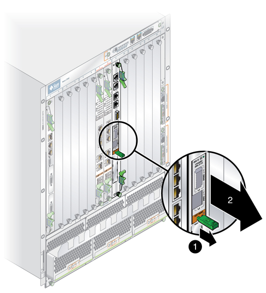
At the front of the blade server, locate the AMC you want to remove.
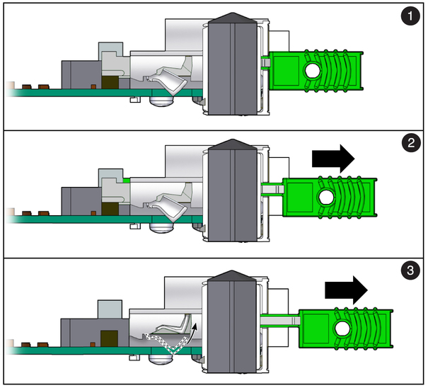
For the AMC, initiate the hot-swap deactivation sequence by pulling the injector/ejector latch out half way, as shown in the figure.
The Hot-Swap LED starts blinking.
Wait until the Hot-Swap LED is solid blue.
When the Hot-Swap LED is solid blue, pull the injector/ejector latch out completely, as shown in the figures.

Figure Legend
1 Fully In (IN) When IN, the module communicates to the shelf manager that the module is not in the hot-swap state, and the shelf manager communicates with the MMC. This position is for normal operation.
2 Half Way (HW) When in the HW position, the hot-swap sequence is initiated. The MMC sends a hot-swap event to the shelf manager.
3 Out (OUT) When OUT, the latching mechanism is released and the module can be extracted. Wait for the Hot-Swap LED to stop blinking before pulling the latch all the way out.

 | Caution - Failure to fill all slots with AMCs or cover with filler panels can negatively impact the cooling of the system. |
Replace the AMC with another AMC or install a filler panel.