JavaScript is required to for searching.
Skip Navigation Links
Exit Print View
StorageTek 4 Gb FC Dual Port ExpressModule HBA From Emulex

Installation Guide For HBA Models SG-XPCIE2FC-EB4-Z and SG-PCIE2FC-EB4-Z

search filter icon
search icon

Document Information

Preface

1.  HBA Overview

HBA Features and Specifications

System Interoperability

Host Platform Support

Storage System Support

Fibre Channel Switch Support

Operating System Requirements

2.  Hardware Installation and Removal

Observing ESD and Handling Precautions

Installing the Hardware

To Install the HBA

To Connect the Optical Cable

To Apply Power

Testing the Installation (Oracle Solaris)

To Verify Proper Installation (Oracle Solaris)

To Verify Attached Storage (Oracle Solaris)

Configuring the HBA for Hot-Plug Operation

Configuring the HBA for Hot-Plug Operation

Removing the Hardware

To Prepare the HBA for Removal Using the HBA Attention Button

To Prepare the HBA for Hot-Plug Removal (for Oracle Solaris)

To Remove the HBA Hardware

3.  HBA Software Installation

Driver Software for the Oracle Solaris OS

Oracle Solaris Diagnostic Support

Installing Software for the Red Hat and SUSE Linux OSs

To Install the HBA Software for Linux OS

Installing Software for Windows Server 2003

To Install the Software for Windows Server 2003

Configuration and Diagnostic Utilities

4.  Release Notes

Oracle Solaris 10 for x64/x86 Operating Systems

Red Hat Enterprise Linux 4 and SUSE Linux Enterprise Server 9 Systems

Windows Server 2003 Operating System

Installing the Hardware

The hardware installation process involves the following general steps:

To Install the HBA

  1. Attach an antistatic strap (refer to Observing ESD and Handling Precautions).
  2. Refer to your system installation or service manual to determine an appropriate ExpressModule slot in which to install the HBA.
  3. Press down the plastic tab to release the ExpressModule latch and pull the lever out until it is nearly perpendicular with the ExpressModule front panel.

    Figure 2-1 The HBA With Its Latch Pulled Out
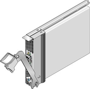
    image:Figure that shows the HBA with its latch pulled out.
  4. Insert the HBA into its slot, being careful that the tooth on the bottom of the lever does not come in contact with the chassis sheet metal during insertion.
  5. When the HBA is inserted nearly all the way into its slot, push the lever back into its fully closed position, allowing the lever tooth to insert the HBA fully into place.

To Connect the Optical Cable

  1. Use multimode fiber-optic cable, intended for short-wave lasers, that adheres to the specifications in the following table.

    Note - The HBA does not allow normal data transmission on an optical link unless it is connected to another similar or compatible Fibre Channel (FC) product (that is, multimode to multimode).


    Fiber-Optic Cable
    Maximum Length
    Minimum Length
    Connector
    62.5/125 mm (multimode)
    300 meters at 1.0625 Gbps

    150 meters at 2.125 Gbps

    70 meters at 4.25 Gbps

    2 meters
    LC
    50/125 mm (multimode)
    500 meters at 1.0625 Gbps

    300 meters at 2.125 Gbps

    150 meters at 4.25 Gbps

    2 meters
    LC
  2. Connect the fiber-optic cable to an LC connector on the HBA.

    Figure 2-2 Two Optical Cables Connecting to the HBA
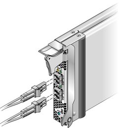
    image:The figure shows two optical cables connecting to the HBA.
  3. Connect the other end of the fiber-optic cable to the FC device.

    After the optical cable is connected to the HBA, you are ready to apply power to the system. If power is already applied to the system, proceed to Configuring the HBA for Hot-Plug Operation.

To Apply Power

  1. Verify that the HBA is securely installed in the system.
  2. Verify that the correct optical cable is attached.
  3. Refer to your system installation or service manual to determine how to power up the system blade.
  4. Observe the light-emitting diodes (LEDs) status for the power-on self test (POST) results as shown in the following table.

    The following table summarizes LED indicator combinations. Refer to LEDs and the Attention Button to determine the location of the LEDs. Each port has a corresponding set of LEDs that provide a visual indication of the operating state.


    Green LED
    Yellow LED
    State
    On
    1 fast blink
    1-Gb link rate - Normal operating state, link up
    On
    2 fast blinks
    2-Gb link rate - Normal operating state, link up
    On
    3 fast blinks
    4-Gb link rate - Normal operating state, link up
    Off
    Off
    Wake-up failure (failed board)
    Off
    On
    POST failure (failed board)
    Off
    Slow blink
    Wake-up failure monitor
    Off
    Fast blink
    Failure in POST
    Off
    Flashing
    POST processing in progress
    On
    Off
    Failure while functioning
    On
    On
    Failure while functioning
    Slow blink
    Off
    Normal - link down
    Slow blink
    On
    Not defined
    Slow blink
    Slow blink
    Off-line for download
    Slow blink
    Fast blink
    Restricted off-line mode (waiting for restart)
    Slow blink
    Flashing
    Restricted off-line mode, test active

    Figure 2-3 LEDs and the Attention Button

    image:Figure that shows the LEDs and Attention button.