IPMP Support in Oracle Solaris
-
IPMP enables you to configure multiple IP interfaces into a single group, called an IPMP group. As a whole, the IPMP group with its multiple underlying IP interfaces is represented as a single IPMP interface. This interface is treated just like any other interface on the IP layer of the network stack. All IP administrative tasks, routing tables, Address Resolution Protocol (ARP) tables, firewall rules, and other IP-related procedures work with an IPMP group by referring to the IPMP interface.
Note - Although Oracle Solaris supports the use of iSCSI devices with IPMP, a server that boots from an iSCSI device cannot be part of an IPMP group. -
The system handles the distribution of data addresses amongst the underlying active interfaces. When the IPMP group is created, data addresses belong to the IPMP interface as an address pool. The kernel then automatically and randomly binds the data addresses to the underlying active interfaces of the group.
-
You primarily use the ipmpstat command to obtain information about IPMP groups. This command provides information about all aspects of the IPMP configuration, such as the underlying IP interfaces of the group, test and data addresses, types of failure detection being used, and which interfaces have failed. The ipmpstat command functions, the options that you can use, and the output that each option generates are all described in Monitoring IPMP Information.
-
You can assign an IPMP interface a customized name to identify the IPMP group more easily. See Configuring IPMP Groups.
IPMP provides the following support:
Benefits of Using IPMP
Different factors can cause an interface to become unusable, such as an interface failure or interfaces being taken offline for maintenance. Without IPMP, the system can no longer be contacted by using any of the IP addresses that are associated with that unusable interface. Additionally, existing connections that use those IP addresses are disrupted.
With IPMP, you can configure multiple IP interfaces into an IPMP group. The group functions like an IP interface with data addresses to send or receive network traffic. If an underlying interface in the group fails, the data addresses are redistributed amongst the remaining underlying active interfaces in the group. Thus, the group maintains network connectivity despite an interface failure. With IPMP, network connectivity is always available, provided that a minimum of one interface is usable for the group.
IPMP also improves overall network performance by automatically spreading outbound network traffic across the set of interfaces within the IPMP group. This process is called outbound load spreading. The system also indirectly controls inbound load spreading by performing source address selection for packets whose IP source address was not specified by the application. However, if an application has explicitly chosen an IP source address, then the system does not vary that source address.
In this release, outbound load spreading occurs on a per-connection basis, rather than on a next hop basis as in previous releases. This change greatly improves IPMP capabilities by enabling two different connections to the same off-link destination by using different outbound interfaces.
Link aggregations perform functions that are similar to IPMP to improve network performance and availability. To compare these two technologies, see Appendix A, Link Aggregations and IPMP: Feature Comparison, in Managing Network Datalinks in Oracle Solaris 11.3.
Rules for Using IPMP
IPMP group configuration is determined by your specific system configuration.
Observe the following rules for IPMP configuration:
-
Multiple IP interfaces that are on the same LAN must be configured into an IPMP group. A LAN broadly refers to a variety of local network configurations, including VLANs and both wired and wireless local networks with nodes that belong to the same link-layer broadcast domain.
Note - Multiple IPMP groups on the same link layer (L2) broadcast domain are unsupported. An L2 broadcast domain typically maps to a specific subnet. Therefore, you must configure only one IPMP group per subnet. Note also that some exceptions to this rule apply, for example, in the case of certain engineered systems that are provided by Oracle. For further clarification, contact your Oracle support representative. -
Underlying IP interfaces of an IPMP group must not span different LANs.
For example, suppose that a system with three interfaces is connected to two separate LANs. Two IP interfaces connect to one LAN while a single IP interface connects to the other LAN. In this case, the two IP interfaces connecting to the first LAN must be configured as an IPMP group, as required by the first rule. In compliance with the second rule, the single IP interface that connects to the second LAN cannot become a member of that IPMP group. No IPMP configuration is required for the single IP interface. However, you can configure the single interface into an IPMP group to monitor the interface's availability. Single-interface IPMP configuration is discussed further in Types of IPMP Interface Configurations.
Consider another case where the link to the first LAN consists of three IP interfaces while the other link consists of two interfaces. This setup requires the configuration of two IPMP groups: a three-interface group that connects to the first LAN, and a two-interface group that connects to the second LAN.
-
All interfaces in the same group must have the same STREAMS modules configured in the same order. When planning an IPMP group, first check the order of STREAMS modules on all interfaces in the prospective IPMP group, then push the modules of each interface in the standard order for the IPMP group. To print a list of STREAMS modules, use the ifconfig interface modlist command. For example, here is the ifconfig output for a net0 interface:
# ifconfig net0 modlist
0 arp
1 ip
2 e1000g
As the previous output shows, interfaces normally exist as network drivers directly below the IP module. These interfaces do not require additional configuration. However, certain technologies are pushed as STREAMS modules between the IP module and the network driver. If a STREAMS module is stateful, then unexpected behavior can occur on failover, even if you push the same module to all of the interfaces in a group. However, you can use stateless STREAMS modules, provided that you push them in the same order on all interfaces in the IPMP group.
The following example shows the command you might use to use to push the modules of each interface in the standard order for the IPMP group:
# ifconfig net0 modinsert vpnmod@3
For step-by-step instructions on planning an IPMP group, see How to Plan an IPMP Group.
IPMP Components
-
Multipathing daemon (in.mpathd) – Detects interface failures and repairs. The daemon performs both link-based failure detection and probe-based failure detection if test addresses are configured for the underlying interfaces. Depending on the type of failure detection method that is used, the daemon sets or clears the appropriate flags on the interface to indicate whether the interface failed or has been repaired. As an option, you can also configure the daemon to monitor the availability of all interfaces, including interfaces that are not configured to belong to an IPMP group. For a description of failure detection, see Failure Detection in IPMP.
The in.mpathd daemon also controls the designation of active interfaces in the IPMP group. The daemon attempts to maintain the same number of active interfaces that was originally configured when the IPMP group was created. Thus, in.mpathd activates or deactivates underlying interfaces as needed to be consistent with the administrator's configured policy. For more information about how the in.mpathd daemon manages the activation of underlying interfaces, see How IPMP Works. For more information about the daemon, refer to the in.mpathd(1M) man page.
-
IP kernel module – Manages outbound load spreading by distributing the set of available IP data addresses in the IPMP group across the set of available underlying IP interfaces in the group. The module also performs source address selection to manage inbound load spreading. Both roles of the module improve network traffic performance.
-
IPMP configuration file (/etc/default/mpathd) – Defines the daemon's behavior.
-
Target interfaces to probe when running probe-based failure detection
-
Time duration to probe a target to detect failure
-
Status with which to flag a failed interface after that interface is repaired
-
Scope of IP interfaces to monitor, whether to also include IP interfaces in the system that are not configured to belong to IPMP groups
You customize the file to set the following parameters:
For information about how to modify the configuration file, see How to Configure the Behavior of the IPMP Daemon.
-
-
ipmpstat command – Provides different types of information about the status of IPMP as a whole. The tool also displays other information about the underlying IP interfaces for each IPMP group, as well as data and test addresses that have been configured for the group. For more information about this command, see Monitoring IPMP Information and the ipmpstat(1M) man page.
The following are the IPMP software components:
Types of IPMP Interface Configurations
An IPMP configuration typically consists of two or more physical interfaces on the same system that are attached to the same LAN.
-
Active-active configuration – An IPMP group in which all underlying interfaces are active. An active interface is an IP interface that is currently available for use by the IPMP group.
Note - By default, an underlying interface becomes active when you configure the interface to become part of an IPMP group. -
Active-standby configuration – An IPMP group in which at least one interface is administratively configured as a standby interface. Although idle, the standby interface is monitored by the multipathing daemon to track the interface's availability, depending on how the interface is configured. If link-failure notification is supported by the interface, link-based failure detection is used. If the interface is configured with a test address, probe-based failure detection is also used. If an active interface fails, the standby interface is automatically deployed as needed. You can configure as many standby interfaces as are needed for an IPMP group.
These interfaces can belong to an IPMP group in either of the following configurations:
You can also configure a single interface as its own IPMP group. The single-interface IPMP group behaves the same as an IPMP group with multiple interfaces. However, this IPMP configuration does not provide high availability for network traffic. If the underlying interface fails, then the system loses all capability to send or receive traffic. The purpose of configuring a single-interface IPMP group is to monitor the availability of the interface by using failure detection. By configuring a test address on the interface, the multipathing daemon can track the interface by using probe-based failure detection.
Typically, a single-interface IPMP group configuration is used with other technologies that have broader failover capabilities, such as the Oracle Solaris Cluster software. The system can continue to monitor the status of the underlying interface, but the Oracle Solaris Cluster software provides the functionality to ensure availability of the network when a failure occurs. For more information about the Oracle Solaris Cluster software, see Oracle Solaris Cluster 4.3 Concepts Guide.
An IPMP group without underlying interfaces can also exist, for example, a group with underlying interfaces that have been removed. The IPMP group is not destroyed, but the group can no longer be used to send and receive traffic. As underlying interfaces are brought online for the group, then the data addresses of the IPMP interface are allocated to these interfaces and the system resumes hosting network traffic.
How IPMP Works
IPMP maintains network availability by attempting to preserve the same number of active and standby interfaces that was originally configured when the IPMP group was created.
IPMP failure detection can be link-based, probe-based, or both to determine the availability of a specific underlying IP interface in the group. If IPMP determines that an underlying interface has failed, then that interface is flagged as failed and is no longer usable. The data IP address that was associated with the failed interface is then redistributed to another functioning interface in the group. If available, a standby interface is also deployed to maintain the original number of active interfaces.
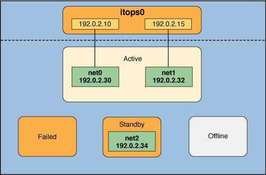
Consider a three-interface IPMP group, itops0, with an active-standby configuration, as illustrated in the following figure.
Figure 1 IPMP Active-Standby Configuration

-
Two data addresses are assigned to the group: 192.0.2.10 and 192.0.2.15.
-
Two underlying interfaces are configured as active interfaces and are assigned flexible link names: net0 and net1.
-
The group has one standby interface, also with a flexible link name: net2.
-
Probe-based failure detection is used, and thus the active and standby interfaces are configured with test addresses as follows:
-
net0: 192.0.2.30
-
net1: 192.0.2.32
-
net2: 192.0.2.34
-
The IPMP group itops0 is configured as follows:
Note - The Active, Offline, Standby, and Failed areas in IPMP Active-Standby Configuration, Interface Failure in IPMP, Standby Interface Failure in IPMP, and IPMP Recovery Process indicate only the status of underlying interfaces and not the physical locations. No physical movement of interfaces or addresses, or any transfer of IP interfaces, occurs within this IPMP implementation. The areas only serve to show how an underlying interface changes status as a result of either failure or repair.
You can use the ipmpstat command with different options to display specific types of information about existing IPMP groups. For additional examples, see Monitoring IPMP Information.
The following command displays information about the IPMP configuration in IPMP Active-Standby Configuration:
# ipmpstat -g
GROUP     GROUPNAME     STATE     FDT        INTERFACES
itops0    itops0        ok        10.00s     net1 net0 (net2)
You would display information about the group's underlying interfaces as follows:
# ipmpstat -i
INTERFACE   ACTIVE     GROUP     FLAGS      LINK        PROBE     STATE
net0        yes        itops0    -------    up          ok        ok
net1        yes        itops0    --mb---    up          ok        ok
net2        no         itops0    is-----    up          ok        ok
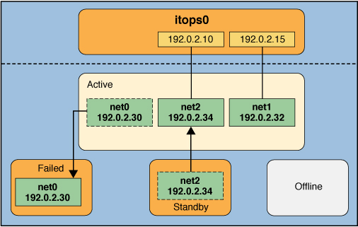
IPMP maintains network availability by managing the underlying interfaces to preserve the original number of active interfaces. Thus, if net0 fails, then net2 is deployed to ensure that the IPMP group continues to have two active interfaces. The net2 activation is shown in the following figure.
Figure 2 Interface Failure in IPMP

Note - The one-to-one mapping of data addresses to active interfaces in Interface Failure in IPMP serves only to simplify the illustration. The IP kernel module can randomly assign data addresses without necessarily adhering to a one-to-one relationship between data addresses and interfaces.
The ipmpstat command displays the information in the figure as follows:
# ipmpstat -i
INTERFACE   ACTIVE     GROUP     FLAGS      LINK        PROBE     STATE
net0        no         itops0    -------    up          failed    failed
net1        yes        itops0    --mb---    up          ok        ok
net2        yes        itops0    -s-----    up          ok        ok
After net0 is repaired, it reverts to its status as an active interface. In turn, net2 is returned to its original standby status.
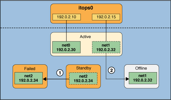
A different failure scenario is shown in Standby Interface Failure in IPMP, where the standby interface net2 fails (1). Later, one active interface, net1, is taken offline by the administrator (2). The result is that the IPMP group is left with a single functioning interface, net0.
Figure 3 Standby Interface Failure in IPMP

The ipmpstat command displays the information in the figure as follows:
# ipmpstat -i
INTERFACE   ACTIVE     GROUP     FLAGS       LINK        PROBE     STATE
net0        yes        itops0    -------     up          ok        ok
net1        no         itops0    --mb-d-     up          ok        offline
net2        no         itops0    is-----     up          failed    failed
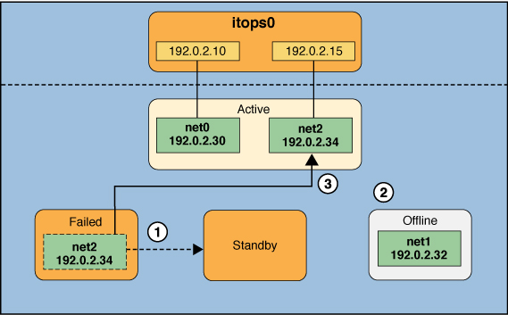
For this particular failure, the recovery process after an interface is repaired is different. The recovery process depends on the IPMP group's original number of active interfaces compared with the configuration after the repair. The following figure represents the recovery process.
Figure 4 IPMP Recovery Process

In IPMP Recovery Process, when net2 is repaired, it would normally revert to its original status as a standby interface (1). However, the IPMP group would still not reflect the original number of two active interfaces because net1 continues to remain offline (2). Thus, IPMP instead deploys net2 as an active interface (3).
The ipmpstat command displays the post-repair IPMP scenario as follows:
# ipmpstat -i
INTERFACE   ACTIVE     GROUP     FLAGS       LINK        PROBE     STATE
net0        yes        itops0    -------     up          ok        ok
net1        no         itops0    --mb-d-     up          ok        offline
net2        yes        itops0    -s-----     up          ok        ok
A similar recovery process occurs if the failure involves an active interface that is also configured in FAILBACK=no mode, where a failed active interface does not automatically revert to active status upon repair. Suppose that net0 in Interface Failure in IPMP is configured in FAILBACK=no mode. In that mode, a repaired net0 becomes a standby interface, even though it was originally an active interface. The interface net2 remains active to maintain the IPMP group's original number of two active interfaces.
The ipmpstat command displays the recovery information as follows:
# ipmpstat -i
INTERFACE   ACTIVE     GROUP     FLAGS      LINK        PROBE     STATE
net0        no         itops0    i------    up          ok        ok
net1        yes        itops0    --mb---    up          ok        ok
net2        yes        itops0    -s-----    up          ok        ok
For more information about this type of configuration, see FAILBACK=no Mode.