Overview of Deploying VLANs
A virtual local area network (VLAN) is a subdivision of a local area network at the datalink layer of the protocol stack. You can create VLANs for local area networks that use switch technology. You can assign interfaces on the same system to different VLANs.
In Oracle Solaris, the elastic virtual switch (EVS) forms the back end for OpenStack networking. EVS facilitates communication between VM instances that are either on VLANs or VXLANs. For more information about OpenStack in Oracle Solaris, see Installing and Configuring OpenStack (Havana) in Oracle Solaris.
In Oracle VM Server for SPARC, the network infrastructure supports 802.1Q VLAN-Tagging. The virtual switch (vsw) and virtual network (vnet) devices support switching of Ethernet packets based on the VLAN ID and handle the necessary tagging or untagging of Ethernet frames. You can use the dladm and ipadm commands to create a VLAN interface over a virtual network device in the guest domains. For more information, see Using VLAN Tagging in Oracle VM Server for SPARC 3.3 Administration Guide.
When to Use VLANs
-
Create a logical division of workgroups.
For example, if all systems on a floor of a building are connected on one switch-based local network, you could create a separate VLAN for each workgroup on the floor.
-
Enforce differing security policies for the workgroups.
For example, the security requirements of a finance department and an information technology department are quite different. You can create a separate VLAN for each department and enforce the appropriate security policy on a per-VLAN basis.
-
Reduce the size of broadcast domain and improve network efficiency. You can split workgroups into manageable broadcast domains.
For example, in a broadcast domain consisting of 25 users, if the broadcast traffic is intended only for 12 users, then setting up a separate VLAN for those 12 users can reduce traffic and improve network efficiency.
You can deploy VLANs if you need to do the following:
Assigning VLAN Names
VLANs demonstrate the advantage of using generic or customized names. In previous releases, the VLAN was identified by the physical point of attachment (PPA) that required combining the hardware-based name of the datalink and the VLAN ID. However, now in Oracle Solaris, you can select a more meaningful name to identify the VLAN. The name must conform to the rules for naming datalinks that are provided in Rules for Valid Link Names in Configuring and Managing Network Components in Oracle Solaris 11.3. For example, you can assign a custom VLAN name such as sales0 or marketing1.
VLAN names work in conjunction with VLAN IDs. Each VLAN in a local area network is identified by a VLAN ID, which is a part of the VLAN tag. The VLAN ID is assigned during VLAN configuration. When you configure switches to support VLANs, you need to assign a VLAN ID to each port. The VLAN ID on the port must be the same as the VLAN ID assigned to the interface that connects to the port.
By default, each port has a VLAN ID called Port VLAN ID. The packets that belong to this VLAN ID are not tagged with a VLAN tag. In Oracle Solaris, you can use the datalink property default_tag to display and change Port VLAN ID on an interface.
VLAN Topology
Switched LAN technology enables you to organize systems on a local network into VLANs. Before you divide a local network into VLANs, you must obtain switches that support the VLAN technology. You can configure all ports on a switch to serve a single VLAN or multiple VLANs, depending on the VLAN topology. Each switch manufacturer has different procedures for configuring ports on a switch. Oracle Switch ES1-24 supports VLAN technology. For more information about configuration of VLAN on Oracle Switch ES1-24, see Sun Ethernet Fabric Operating System, VLAN Administration Guide.
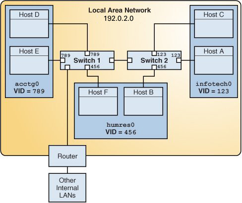
The following figure shows a local area network that has been divided into three VLANs.
Figure 8 Local Area Network With Three VLANs

In the illustration, the LAN has the subnet address 192.0.2.0.
-
acctg0 with VLAN ID 789 – Accounting group. This group owns Host D and Host E.
-
humres0 with VLAN ID 456 – Human Resources group. This group owns Host B and Host F.
-
infotech0 with VLAN ID 123 – Information Technology group. This group owns Host A and Host C.
This LAN is subdivided into three VLANs to correspond with three workgroups:
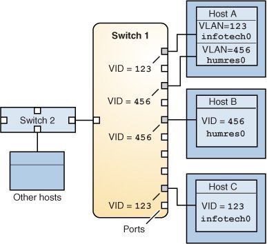
A variation of previous figure is shown in the following figure, where only one switch is used and multiple hosts belonging to different VLANs connect to that single switch.
Figure 9 A Switch Connecting Multiple Hosts of Different VLANs

In the figure, Host A and Host C belong to the Information Technology VLAN with the VLAN ID 123. One of Host A's interface is configured with the VLAN ID 123. This interface connects to Port 1 on Switch 1, which is also configured with the VLAN ID 123. Host B is a member of the Human Resources VLAN with the VLAN ID 456. Host B's interface connects to Port 5 on Switch 1, which is configured with the VLAN ID 456. Finally, the interface of Host C is configured with the VLAN ID 123. The interface connects to Port 9 on Switch 1. Port 9 is also configured with the VLAN ID 123.
The illustration also shows that a single host can belong to multiple VLANs. For example, Host A has two VLANs configured over the interface of the host. The second VLAN is configured with the VLAN ID 456 and is connected to Port 3 that is configured with the VLAN ID 456. Therefore, Host A is a member of both the infotech0 and the humres0 VLANs.