Datalink Multipathing Aggregations
Datalink multipathing (DLMP) aggregation is a type of link aggregation that provides high availability across multiple switches without requiring switch configuration. DLMP aggregation supports link-based failure detection and probe-based failure detection to ensure continuous availability of the network to send and receive traffic.
Advantages of DLMP Aggregation
DLMP aggregation provides the following advantages:
-
The IEEE 802.3ad standard implemented by trunk aggregations does not have provisions to span multiple switches. Allowing failover between multiple switches in trunk mode requires vendor-proprietary extensions on the switches that are not compatible between vendors. DLMP aggregations allow failover between multiple switches without requiring any vendor-proprietary extensions.
-
Using IPMP for high availability in the context of network virtualization is very complex. An IPMP group cannot be assigned directly to a zone. When network interface cards (NICs) have to be shared between multiple zones, you have to configure VNICs so that each zone gets one VNIC from each of the physical NICs. Each zone must group its VNICs into an IPMP group to achieve high availability. The complexity increases as you scale configurations, for example, in a scenario that includes large numbers of systems, zones, NICs, virtual NICs (VNICs), and IPMP groups. With DLMP aggregations, you create a VNIC or configure a zone's anet resource on top of the aggregation, and the zone sees a highly available VNIC.
-
DLMP aggregation enables you to use the features of link layer such as link protection, user-defined flows, and the ability to customize link properties, such as bandwidth.
Note - You can configure an IPMP group over a DLMP aggregation and trunk aggregation. However there are some restrictions when you configure IPMP group over a DLMP aggregation. For more information, see Configuring IPMP Over DLMP in a Virtual Environment for Enhancing Network Performance and Availability.
How DLMP Aggregation Works
In a trunk aggregation, each port is associated with every configured datalink over the aggregation. In a DLMP aggregation, a port is associated with any of the aggregation's configured datalinks.
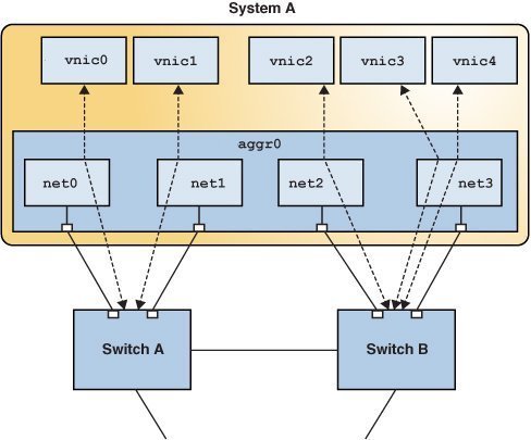
The following figure shows how a DLMP aggregation works.
Figure 4 DLMP Aggregation

The figure shows System A with link aggregation aggr0. The aggregation consists of four underlying links, from net0 to net3. VNICs vnic0 through vnic4 are also configured over the aggregation. The aggregation is connected to Switch A and Switch B, which in turn connect to other destination systems in the wider network.
VNICs are associated with aggregated ports through the underlying links. For example, in the figure, vnic0 through vnic3 are associated with the aggregated ports through the underlying links net0 through net3. That is, if the number of VNICs and the number of underlying links are equal, then each port is associated with an underlying link.
If the number of VNICs exceeds the number of underlying links, then one port is associated with multiple datalinks. For example, in the figure the total number of VNICs exceeds the number of underlying links. Hence, vnic4 shares a port with vnic3.
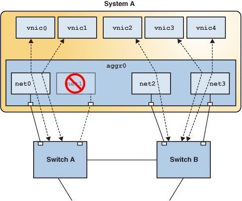
When an aggregated port fails, all the datalinks that use that port are distributed among the other ports, thereby providing network high availability during failover. For example, if net0 fails, then DLMP aggregation shares the remaining port net1, between VNICs. The distribution among the aggregated ports occurs transparently to the user and independently of the external switches connected to the aggregation.
The following figure shows how DLMP aggregation works when a port fails. In the figure, net1 has failed and the link between switch and net1 is down. vnic1 shares a port with vnic0 through net0.
Figure 5 DLMP Aggregation When a Port Fails

Failure Detection in DLMP Aggregation
Failure detection in DLMP aggregation is a method to detect the failure of the aggregated ports. A port is considered to have failed when it cannot send or receive traffic. The port might fail because of the following reasons:
-
Damage or cut in the cable
-
Switch port goes down
-
Failure in upstream network path
DLMP aggregation performs failure detection on the aggregated ports to ensure continuous availability of the network to send or receive traffic. When a port fails, the clients associated with that port are failed over to an active port. Failed aggregated ports remain unusable until they are repaired. The remaining active ports continue to function while any existing ports are deployed as needed. After the failed port recovers from the failure, clients from other active ports can be associated with it.
DLMP aggregation supports both link-based and probe-based failure detection.
Link-Based Failure Detection
Link-based failure detection detects failure when the cable is cut or when the switch port is down. It therefore can only detect failures caused by the loss of direct connection between the datalink and the first-hop switch. Link-based failure detection is enabled by default when a DLMP aggregation is created.
Probe-Based Failure Detection
Probe-based failure detection detects failures between an end system and the configured target IP addresses. This feature overcomes the known limitations of link-based failure detection. Probe-based failure detection is useful when a default router is down or when the network becomes unreachable. The DLMP aggregation detects failure by sending and receiving probe packets.
To enable probe-based failure detection in DLMP aggregation, you must configure the probe-ip property.
Note - In a DLMP aggregation, if no probe-ip is configured, then probe-based failure detection is disabled and only link-based failure detection is used.
Probe-based failure detection is performed by using the combination of two types of probes: Internet Control Message Protocol (ICMP (L3)) probes and transitive (L2) probes, which work together to determine the health of the aggregated physical datalinks.
-
ICMP probing operates by sending ICMP packets to a target IP address. You can specify the source and target IP addresses manually or let the system choose them. If a source address is not specified, the source address is chosen from the IP addresses that are configured on the DLMP aggregation or on a VNIC configured on the DLMP aggregation. If a target address is not specified, the target address is chosen from one of the next hop routers on the same subnet as one of the specified source IP addresses. For more information, see How to Configure Probe-Based Failure Detection for DLMP.
-
Transitive probing is performed when the health state of all network ports cannot be determined by using only ICMP probing. This can happen if the source IP addresses chosen for ICMP probing are not on the list of addresses that are configured on a particular port. As a result, this port cannot receive ICMP probe replies. Transitive probing works by sending an L2 packet out of the ports without a configured source IP address to another port that has a configured source IP address. If the other port can reach the ICMP target and the ports sending the transitive probe receive the L2 reply from the other port, it means that the port sending the transitive probe can also reach the ICMP target.
In a DLMP aggregation, you can optionally specify a VLAN that can be used for both ICMP and transitive probing to support configurations where untagged traffic is restricted. You can specify a single VLAN ID by using the probe-vlan-id property and the specified VLAN will be used for both sending the ICMP probes to the target IP and to check the health of the member ports that depend on the transitive probes. The L3 probe target will be automatically selected and validated based on this property. You can provide a value between 0 and 4094 for the probe-vlan-id property. The default value is 0, which indicates that the probes are untagged.
Oracle Solaris includes proprietary protocol packets for transitive probes that are transmitted over the network. For more information, see Packet Format of Transitive Probes.