
When the expansion rack is in its allocated space in the data center, its infrastructure components must be cabled and configured to integrate with the existing Oracle PCA environment. This section explains how to modify the default configuration of the Ethernet and InfiniBand switches and properly connect the cables between the racks.
Reconfiguring the network components requires a serial cable and a laptop or console.
When the rack infrastructure components have booted, you must change their default configuration so that the Oracle PCA Controller Software recognizes them as expansion rack components.
The passwords for the network components in the expansion rack are not managed by the Controller Software. They must be set manually during configuration. It is recommended not to change these passwords once they are set.
Configuring the Ethernet Switches
Connect a serial cable to the Oracle Switch ES1-24 you intend to reconfigure.
NoteEthernet switch A is on the left hand side, and switch B on the right hand side, when looking from the back of the rack.
Log in to the service console with the default credentials:
root/Welcome1.NoteIf the password was modified, reset it first by running set /SP/users/root password.
Set the correct host name.
cd /SP set hostname=
ovcasw18ar2The host name in this example is for Ethernet Switch A in rack 2. Select the correct host name form this list:
Rack 2, switch A:
ovcasw18ar2Rack 2, switch B:
ovcasw18br2Rack 3, switch A:
ovcasw18ar3Rack 3, switch B:
ovcasw18br3
Configure the inband network settings.
cd /SP/inband_network set pendingipaddress=
192.168.4.220set pendingipnetmask=255.255.255.0 set pendingipgateway=192.168.4.201The IP address in this example is for Ethernet Switch A in rack 2. Select the correct IP address form this list:
Rack 2, switch A:
192.168.4.220Rack 2, switch B:
192.168.4.221Rack 3, switch A:
192.168.4.222Rack 3, switch B:
192.168.4.223
Commit and enable your changes.
set commitpending=True
set state=enabled
Configure the NTP service.
set /SP/clients/ntp/server/1/ address=192.168.4.3
set /SP/clients/ntp/server/2/ address=192.168.4.4
set /SP/clock/ usentpserver=enabled
Exit the console and repeat these steps for any other Ethernet switches that must be reconfigured.
Configuring the InfiniBand Switches
Connect a serial cable to the NM2-36P Sun Datacenter InfiniBand Expansion Switch you intend to reconfigure.
Log in with the default credentials:
root/Welcome1.Launch the Service Processor shell by entering the command spsh.
NoteIf the password was modified, reset it first by running set /SP/users/root password.
Set the correct host name.
cd /SP set hostname=
ovcasw16r2The host name in this example is for the InfiniBand Switch in rack unit 16 of rack 2. Select the correct host name form this list:
Rack 2, RU16:
ovcasw16r2Rack 2, RU20:
ovcasw20r2Rack 3, RU16:
ovcasw16r3Rack 3, RU20:
ovcasw20r3
Set the correct IP address.
cd /SP/network set pendingipaddress=
192.168.4.206The IP address in this example is for the InfiniBand Switch in rack unit 16 of rack 2. Select the correct IP address form this list:
Rack 2, RU16:
192.168.4.206Rack 2, RU20:
192.168.4.207Rack 3, RU16:
192.168.4.208Rack 3, RU20:
192.168.4.209
Commit your changes.
set commitpending=True
Configure the NTP service.
set /SP/clients/ntp/server/1/ address=192.168.4.3
set /SP/clients/ntp/server/2/ address=192.168.4.4
set /SP/clock/ usentpserver=enabled
Exit the console and repeat these steps for any other InfiniBand switches that must be reconfigured.
For correct operation, Oracle PCA base rack and expansion racks must be interconnected exactly as described in this section.
Cables to connect the expansion rack to a base rack are included in the shipment. They are stored under the top cavity of the rack.
For InfiniBand connectivity the two NM2-36P Sun Datacenter InfiniBand Expansion Switches in an expansion rack must be connected to the Oracle Fabric Interconnect F1-15 in the base rack. The cabling topology must match Table 7.2.
Table 7.2 InfiniBand Cabling Connections Between Base Rack and Expansion Racks
From Rack | InfiniBand Switch | Port | To Base Rack | Port |
|---|---|---|---|---|
Expansion Rack 1 | RU20 | 8B | F1-15 RU22 | 15 |
Expansion Rack 1 | RU20 | 9B | F1-15 RU22 | 16 |
Expansion Rack 1 | RU20 | 10B | F1-15 RU22 | 17 |
Expansion Rack 1 | RU20 | 8A | F1-15 RU15 | 15 |
Expansion Rack 1 | RU20 | 9A | F1-15 RU15 | 16 |
Expansion Rack 1 | RU20 | 11B | F1-15 RU15 | 17 |
Expansion Rack 1 | RU16 | 8A | F1-15 RU22 | 5 |
Expansion Rack 1 | RU16 | 9A | F1-15 RU22 | 6 |
Expansion Rack 1 | RU16 | 11B | F1-15 RU22 | 7 |
Expansion Rack 1 | RU16 | 8B | F1-15 RU15 | 5 |
Expansion Rack 1 | RU16 | 9B | F1-15 RU15 | 6 |
Expansion Rack 1 | RU16 | 10B | F1-15 RU15 | 7 |
Expansion Rack 2 | RU20 | 8B | F1-15 RU22 | 12 |
Expansion Rack 2 | RU20 | 9B | F1-15 RU22 | 13 |
Expansion Rack 2 | RU20 | 10B | F1-15 RU22 | 14 |
Expansion Rack 2 | RU20 | 8A | F1-15 RU15 | 12 |
Expansion Rack 2 | RU20 | 9A | F1-15 RU15 | 13 |
Expansion Rack 2 | RU20 | 11B | F1-15 RU15 | 14 |
Expansion Rack 2 | RU16 | 8A | F1-15 RU22 | 2 |
Expansion Rack 2 | RU16 | 9A | F1-15 RU22 | 3 |
Expansion Rack 2 | RU16 | 11B | F1-15 RU22 | 4 |
Expansion Rack 2 | RU16 | 8B | F1-15 RU15 | 2 |
Expansion Rack 2 | RU16 | 9B | F1-15 RU15 | 3 |
Expansion Rack 2 | RU16 | 10B | F1-15 RU15 | 4 |
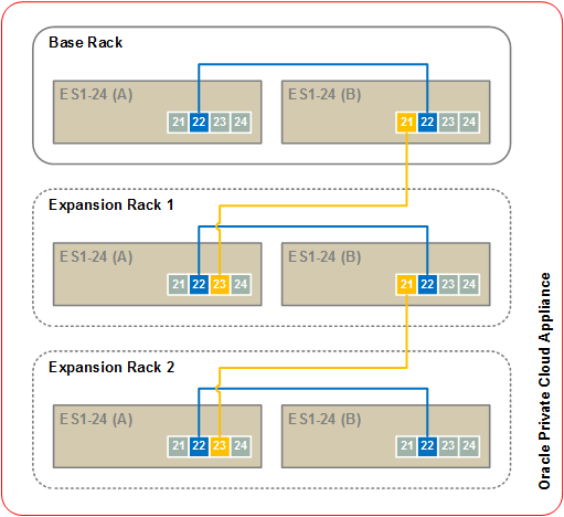
Each rack contains a pair of Oracle Switch ES1-24 Ethernet switches, which are daisy-chained in a multi-rack Oracle PCA environment to form a single internal management network. Proceed as follows:
Disconnect the cables from port 20 on both switches in the expansion rack. This disables the PDU connection to the management network.
Using an SFP+ cable, connect base rack Ethernet switch B port 21 to expansion rack Ethernet switch A port 23.
If a second expansion rack is present, apply the same cabling scheme:
Disconnect the cables from port 20 on both switches.
Connect expansion rack 1 Ethernet switch B port 21 to expansion rack 2 Ethernet switch A port 23.
Figure 7.4 provides a visual representation of inter-rack Ethernet cabling in an Oracle PCA environment with multiple racks.
When all configuration changes have been applied and all cables have been connected, log into the Oracle Private Cloud Appliance Dashboard and click the button in the Hardware View tab. The system powers on and provisions all new compute nodes in the expansion rack(s) and places them in the Oracle VM Unassigned Servers folder.
Use the Oracle PCA command line interface (CLI) to organize the new compute nodes into different tenant groups. These tenant groups then appear as separate server pools in Oracle VM Manager. For details, refer to the section entitled Tenant Groups in the Oracle Private Cloud Appliance Administrator's Guide.