
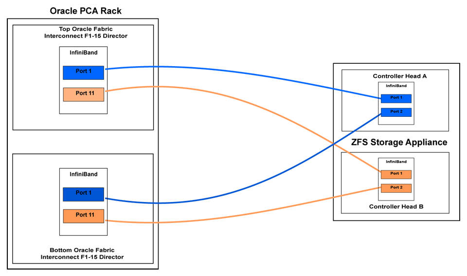
InfiniBand can be used to connect additional ZFS Storage Appliances to the Oracle Private Cloud Appliance (PCA) using the available ports on the Fabric Interconnects. Since ZFS Storage Appliances are dual-headed, each ZFS Controller head has its own InfiniBand connection to each of the Fabric Interconnects, providing redundancy both on the side of the ZFS Storage Appliance and on the side of the Oracle PCA.
The recommended cabling configuration that should be implemented to connect the ZFS appliance to the Oracle PCA cross-connects each controller head to each of the Fabric Interconnects for a total of four connections. This configuration maximizes redundancy and throughput. The following table describes how the cabling should be connected between the Fabric Interconnects on the Oracle PCA and the ZFS Storage Appliance.
Table 9.3 InfiniBand Cabling to Attach a ZFS Storage Appliance
Top Oracle Fabric Interconnect F1-15 (RU 22-25): | Bottom Oracle Fabric Interconnect F1-15 (RU 15-18): | ZFS Storage Appliance Controller Head 1 | ZFS Storage Appliance Controller Head 2 |
|---|---|---|---|
IB Port 1 | IB Port 1 (ibp0) | ||
IB Port 11 | IB Port 1 (ibp0) | ||
IB Port 1 | IB Port 2 (ibp1) | ||
IB Port 11 | IB Port 2 (ibp1) |
This cabling layout is illustrated in the following figure, titled Figure 9.6, “IPoIB Storage Cabling Configuration”.
The following IP address blocks have been reserved for use by a ZFS Storage Appliance external to the Oracle PCA rack:
192.168.40.242
192.168.40.243
192.168.40.244
192.168.40.245
192.168.40.246
192.168.40.247
192.168.40.248
192.168.40.249
This section describes the configuration steps that you must perform on the ZFS Storage Appliance to use IPoIB in conjunction with the Oracle PCA. The description provided here assumes a typical configuration with an active-passive management cluster, using iSCSI to serve LUNs to compute nodes or virtual machines as physical disks. The ZFS Storage Appliance supports a standard NFS configuration as well.
Creating a Basic IPoIB Configuration on a ZFS Storage Appliance
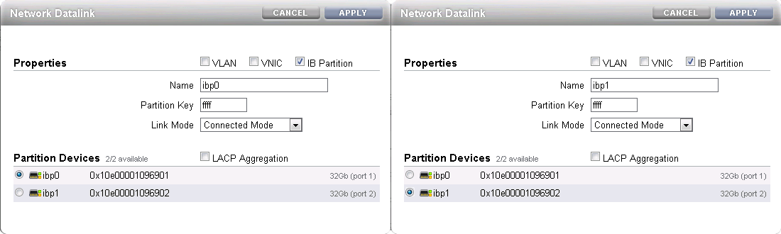
Create Datalinks
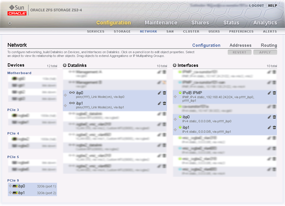
Log on to management user interface on the controller head you intend to use as the master. Go to and then to . If you have cabled correctly, two active devices are listed that map onto the cabled IB ports.
Drag each of these across to the Datalink menu to create a new datalink for each device. Edit each of these datalinks to provide a datalink name and partition key.
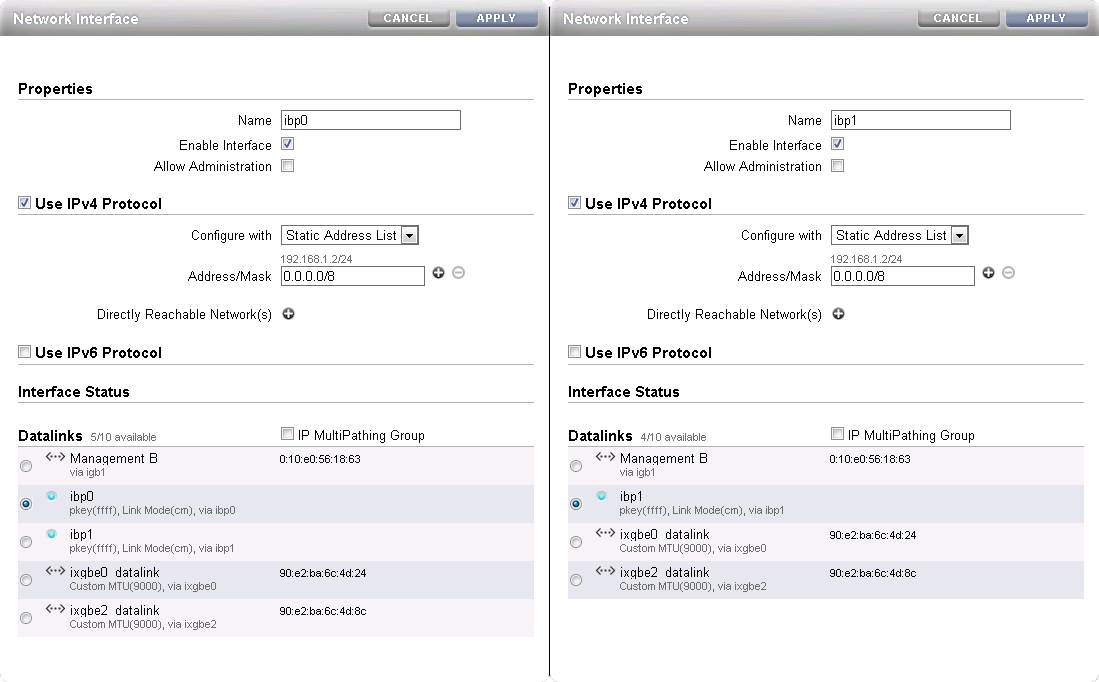
Create Interfaces
Drag each configured datalink across into the Interface menu to create an interface for each datalink that you have defined. Edit each interface to provide a value for the Name field that makes it easy to identify the interface. Add the netmask 0.0.0.0/8 to each interface to prevent the system from probing and testing the routing details behind the network connection. Leave the IP MultiPathing Group unchecked. Do not configure an IP address at this stage.
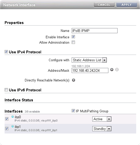
Configure Multipathing
Click the Plus icon in the Interface menu to create an additional interface. This additional interface enables IPMP across the two interfaces you created in the previous step. Enter a value in the Name field that makes it easy to identify the IPMP interface. Assign an IP address from the list of reserved IPs in the Oracle PCA storage network.
Near the bottom of the window, select the IP MultiPathing Group check box. Select the two previously configured interfaces, mark the first one as Active and the second one as Standby. The selected IP address will be configured on the active interface until a failover to the standby interface occurs.
Apply Connectivity Configuration
Click the Apply button to commit the connectivity configuration you performed up to this point. When you select any device, datalink or interface associated with your configuration, all related items are highlighted in the user interface, as shown in the screenshot below. All other items unrelated to the configuration in this procedure have been blurred out in the image.
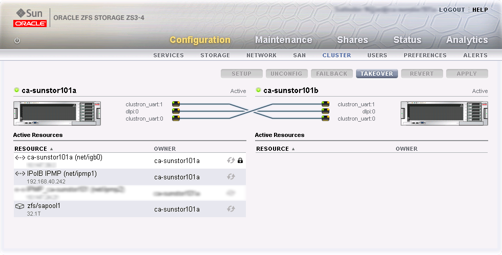
Verify Management Cluster Configuration
The external storage setup proposed in this chapter has an active-passive cluster configuration. Consequently all storage resources for Oracle PCA have to be available at one particular IP address at any time. The IP address and the storage resources are owned by the active head in the management cluster, and the standby head is ready to take over the IP address and expose the same storage resources if the active head should fail.
On the active storage controller, go to and then to . The active-passive cluster configuration is illustrated in the screenshot below. All resources involved in the Oracle PCA external storage setup are owned by the active head: the storage appliance management interface, the IPMP interface configured specifically for Oracle PCA external storage connectivity, and the storage pool where the LUNs will be created.
In this setup the entire configuration is applied on the active controller and automatically replicated on the standby controller. Since all resources are owned by the active head, there is no need to log on to the standby head and make any configuration changes.
Configure iSCSI Targets
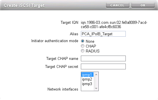
On the active controller, go to , and then to . Click the Plus icon in the Targets menu to create a new iSCSI target. Enter a value in the Alias field that makes it easy to identify the iSCSI target. Select the IPMP interface you configured specifically for Oracle PCA external storage connectivity. Click OK to create the new target.
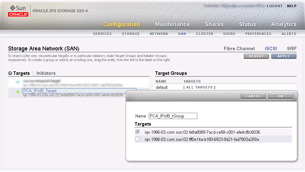
Drag the iSCSI target that you have created into the Target Group area to create a target group. Edit the target group, give it an appropriate name, and make sure the IQN of the correct iSCSI target is selected. Click OK to save your changes.
Configure iSCSI Initiators
First, you need to retrieve the IQN of each compute node you wish to grant access to the external storage. Log on to the master management node of your Oracle PCA and proceed as follows:
Using the CLI, list all compute nodes.
[root@ovcamn05r1 ~]# pca-admin list compute-node

Compute_Node  IP_Address    Provisioning_Status  ILOM_MAC            Provisioning_State
------------  ----------    -------------------  --------            ------------------
ovcacn09r1    192.168.4.7   RUNNING              00:10:e0:3f:82:75   running
ovcacn13r1    192.168.4.11  RUNNING              00:10:e0:3f:87:73   running
ovcacn26r1    192.168.4.13  RUNNING              00:10:e0:3e:46:db   running
ovcacn12r1    192.168.4.10  RUNNING              00:10:e0:3f:8a:c7   running
ovcacn08r1    192.168.4.6   RUNNING              00:10:e0:3f:84:df   running
ovcacn27r1    192.168.4.14  RUNNING              00:10:e0:3f:9f:13   running
ovcacn07r1    192.168.4.5   RUNNING              00:10:e0:3f:75:73   running
ovcacn11r1    192.168.4.9   RUNNING              00:10:e0:3f:83:23   running
ovcacn10r1    192.168.4.8   RUNNING              00:10:e0:3f:89:83   running
ovcacn14r1    192.168.4.12  RUNNING              00:10:e0:3f:8b:5d   running
-----------------
10 rows displayed

Status: Success
SSH into each compute node and display the contents of the file
initiatorname.iscsi.[root@ovcamn05r1 ~]# ssh ovcacn07r1 root@ovcacn07r1's password: [root@ovcacn07r1 ~]# cat /etc/iscsi/initiatorname.iscsi InitiatorName=iqn.1988-12.com.oracle:a72be49151 [root@ovcacn07r1 ~]# exit logout Connection to ovcacn07r1 closed. [root@ovcamn05r1 ~]#
NoteUsing SSH to connect to each of the listed compute nodes is the fastest way to obtain the IQNs. However, they can also be copied from the Oracle VM Manager user interface, in the Storage Initiator perspective for each server.
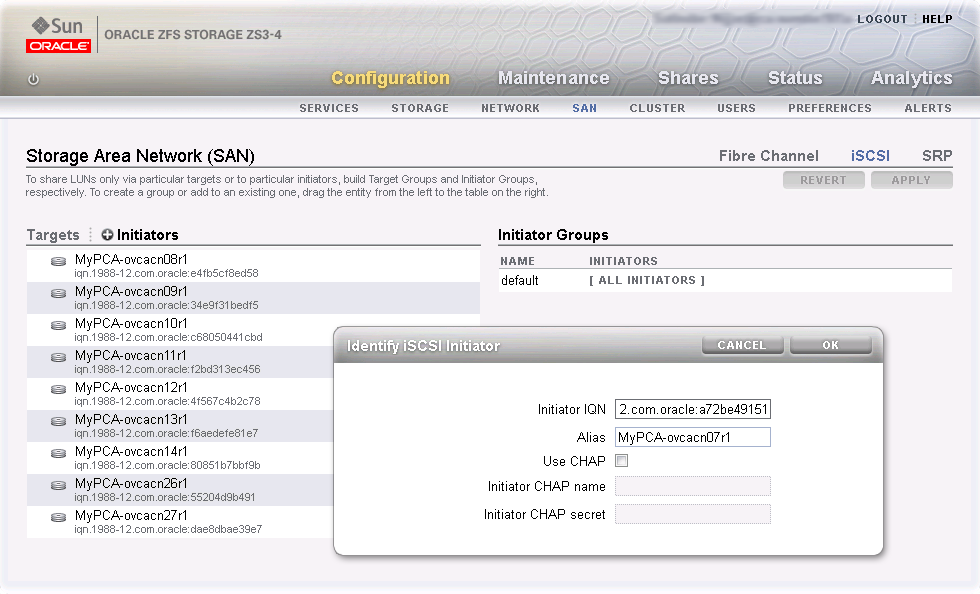
Copy the IQN of the compute node and use it to define a corresponding iSCSI initiator in the ZFS Storage Appliance user interface.
Click on the Initiators link to define the iSCSI initiators for the compute nodes that you wish to expose LUNs to. Click the Plus icon to identify a new iSCSI initiator. Enter the compute node Initiator IQN and an Alias that makes it easy to identify the iSCSI initiator. Repeat this for each compute node so that all initiators appear in the list.
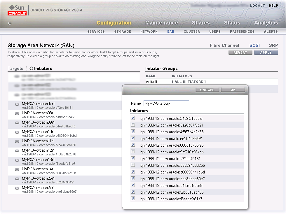
Drag the one of the iSCSI initiators that you have created into the Initiator Group area to create a new initiator group. Edit the initiator group, give it an appropriate name, and make sure that all IQNs of the compute nodes that you want to make a member of this initiator group are selected. Click OK to save your changes.
Apply iSCSI Target and Initiator Configuration
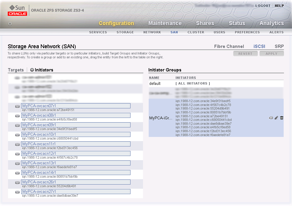
Click the Apply button to commit the iSCSI target and initiator configuration you performed up to this point. When you select any initiator or initiator group associated with your configuration, all related items are highlighted in the user interface, as shown in the screenshot below. Other items unrelated to the configuration in this procedure have been blurred out in the image.
Create a LUN
For easy management it is good practice to organize storage resources in separate projects. Create a project first for your Oracle PCA external storage, and then add LUNs as you need them.
On the active storage controller, go to . On the left hand side, click the Plus icon to create a new Project. In the Create Project dialog box, enter a Name to make it easy to identify the project. Click Apply to save the new project.
In the navigation pane on the left hand side, select the project you just created. In the Shares window, first select LUNs,and then click the Plus icon to create a new LUN as part of this project.
Fill out the LUN properties, select the iSCSI target group and initiator group you created earlier, and enter a Name that makes it easy to identify the LUN. Click Apply to add the LUN to the selected project.


The active-passive configuration explained in detail in this section is the basic supported external storage setup. More elaborate setups with multiple storage appliances and active-active configurations are also possible. Bear in mind, however, that these require additional cabling and therefore also an additional pair of redundant InfiniBand switches. Contact your Oracle representative for more information about other external storage options.
If you wish to access these LUNs as physical disks within Oracle VM Manager, you must configure Oracle VM Manager first. Refer to Section 9.3.4.1, “ISCSI Configuration” for more information.
If you intend to use your ZFS appliance to provide storage for use directly by Oracle VM, to host repositories and virtual machines, you must configure the storage within Oracle VM Manager before you are able to use it. The configuration steps that you must perform depend on whether you have configured iSCSI or NFS on your ZFS Storage Appliance. This section provides a brief outline of the steps that you must perform to configure Oracle VM Manager for each of these technologies. For more detailed information, you should refer to the Oracle VM documentation.
If you only intend to make this storage available to individual virtual machines and do not intend to use the storage for underlying Oracle VM infrastructure, you do not need to perform any of the steps documented in this section, but you will need to configure each virtual machine directly to access the storage either over NFS or iSCSI.
Reprovisioning restores a compute node to a clean state. If a compute node with active connections to external storage repositories is reprovisioned, the external storage connections need to be configured again after reprovisioning.
The following configuration steps should be performed in Oracle VM Manager if you have configured your storage appliance for iSCSI. The process to add a File Server in Oracle VM Manager is clearly documented in the Oracle VM User's Guide for Release 3.2 available at:
http://docs.oracle.com/cd/E35328_01/E35332/html/vmusg-storage-manage.html
Log into Oracle VM Manager on the Oracle PCA
Select the
Storagetab to configure your storageClick on the
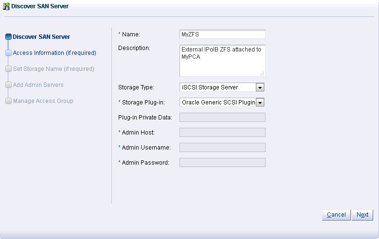
Discover SAN Servericon to load the wizardEnter the DNS name of the storage appliance in the Name field. In the Storage Type field, use the drop-down selector to select
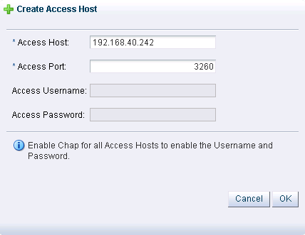
iSCSI Storage Server. In the Storage Plug-in field, you must select theOracle Generic SCSI plugin. Note that alternate storage plugins are not supported in this configuration. Click .In the Access Information dialog, click on the icon that allows you to add a new Access Host. This opens the Create Access Host dialog. Enter the IP address that you configured for the IPMP interface of the storage appliance, for example 192.168.40.242. If you have configured your storage appliance with CHAP access, you must also enter the CHAP username and password here. Click to close the Create Access Host dialog. Click .
In the Add Admin Servers dialog, select all of the servers in the Available Servers frame and move them to the Selected Servers frame. Click .
In the Manage Access Group dialog, click on
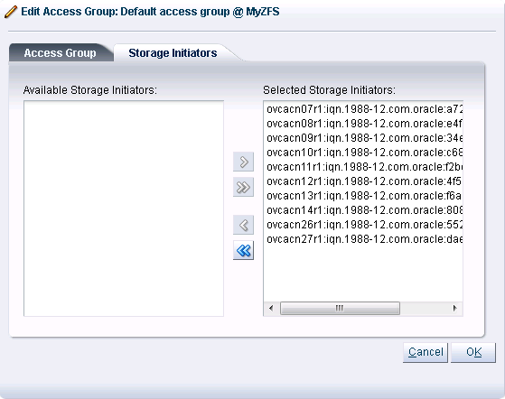
Default Access Groupand then click on the Edit icon. The Edit Access Group dialog is opened. Click on theStorage Initiatorstab. Select the IQN name from all of the initiators that you have configured on the ZFS Storage Appliance and move them into the Selected Storage Initiators pane. Usually it is acceptable to move all of the IQNs across. Click to save the changes.Click the button to exit the wizard and to save your changes.
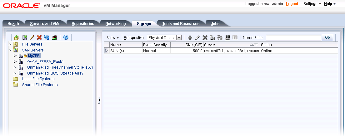
The iSCSI server appears in the SAN Servers tree in the navigation pane. After storage discovery the LUN appears in the Physical Disks perspective.
The following configuration steps should be performed in Oracle VM Manager if you have configured your storage appliance for NFS. The process to add a File Server in Oracle VM Manager is clearly documented in the Oracle VM User's Guide for Release 3.2 available at:
http://docs.oracle.com/cd/E35328_01/E35332/html/vmusg-storage-manage.html
Log into Oracle VM Manager on the Oracle PCA
Select the
Storagetab to configure your storageClick on the
Discover File Servericon to load the wizardEnter all required information into the wizard. Use either one of the IP addresses that you configured for the device as the Access Host IP, for example 192.168.40.242.
Select all of the compute nodes that should be designated as Admin Servers.
Select two or three compute nodes that should be used as Refresh Servers.
Select the file systems that you would like to use.
Click the
Finishbutton.The file server appears in the File Servers tree in the navigation pane.