Power on the Oracle Disk Shelves and Controllers
Power on all Oracle disk shelves and both controllers. While you must make an Oracle ILOM connection to one controller in preparation for initial configuration, make the connection for both controllers and keep them in place for future access to the SPs through Oracle ILOM.
Note - Remote network access is preferred when connecting to Oracle ILOM because it allows better data collection than a direct serial connection. Per your environment, it might be preferable to make a serial connection for the initial configuration, and a network connection thereafter.
- If necessary, extend the controllers to the maintenance position so you can access the back of the controllers.
-
Ensure that each controller has an Ethernet cable connected from your network
to the 10-Gigabit Ethernet NET 1 port on the back panel of the
controller.
To locate the port, see Back Panel Status Indicators, Connectors, and PCIe Slots.
This task should have been performed when attaching cables to the controllers as described in Connect the Data Cables.
-
Connect to both controllers using Oracle ILOM.
Note - It is recommended that you do not disconnect these cables after initial configuration, so there is readily available access to the SPs through Oracle ILOM. It is also recommended that you make a connection to each controller.-
For a network connection, connect an Ethernet cable from the NET 0 port on the back of the controller to your network. This is the preferred connection method to Oracle ILOM for data collection.
-
For a serial connection, connect a serial cable from the SER MGT port on the back of the controller to the serial port on the administrative client. Use a DB9 to RJ45 adapter if necessary. Ensure that the client has been prepared as outlined in Prerequisites.
-
- If using the optional cable management arm (CMA), route all cables, except the controller cluster cables, through the CMA and secure with the Velcro straps.
-
Power on the disk shelf(ves) by plugging the two power cords into the power
supply connectors, connecting the cords to the external power source, applying
external power, and turning on the disk shelf power switch(es) (the
“|” position).
Note - To guarantee redundancy, power cords must be connected to two separate and independent power sources.Wait several minutes until the system power indicator on the front, and the power supply status indicator for each power supply on the back are lit a steady green.
-
There are two power cords for each controller. Connect one end of each
controller power cord to a grounded electrical outlet.
Note - To guarantee redundancy, power cords must be connected to two separate and independent power sources. -
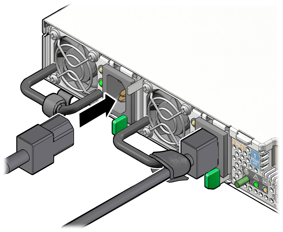
Connect the controller power cords to the power supply AC connectors on the
back panel of the controller and use the Velcro strap to secure them.
Shortly after power is applied to the system, the SP OK LED blinks as the service processor (SP) is booting. The SP OK LED is illuminated solid green after the SP has successfully booted. After the SP has booted, the Power/OK LED on the front panel begins flashing slowly, indicating the host is in standby power mode. In standby power mode, the controller is not yet initialized or powered on.

Note - At this point, power is supplied only to the SP and the power supply fans. After the Power/OK LED is lit a steady green, the controller has full power and is ready for initial configuration. - If after a few minutes the Power/OK LED on the front panel is not lit a steady green, apply the remaining power manually by pressing the Power button on the controller front panel.
-
If you extended the controllers to the maintenance position, push the
controllers into the rack until the slide-rail locks (on the front of the
controllers) engage the slide-rail assemblies.
You will hear an audible click when the controller is in the normal rack position.
