Chapter 8 Extending Oracle Private Cloud Appliance - Additional Storage
Extending the Oracle Private Cloud Appliance by connecting and configuring additional storage can enhance the product by providing the disk space required for large repositories, for backup and recovery storage, and to provision virtual machines with virtual disks beyond the capacity already available on the appliance. This process does not require that the system is powered down, but cabling and configuration must match the Oracle Private Cloud Appliance requirements.
Different generations of the ZFS Storage Appliance have been delivered as part of Oracle Private Cloud Appliance, and the Controller Software continues to provide support for all previous generations. However, there are functional differences between the Oracle ZFS Storage Appliance ZS7-2, which is part of systems with an Ethernet-based network architecture, and the previous models of the ZFS Storage Appliance, which are part of systems with an InfiniBand-based network architecture.
There are options to extend the storage capacity of appliances with either type of network architecture, but the hardware involved and the required connectivity are different. For clarity, this chapter describes the addition of storage capacity separately for each network architecture.
8.1 Extending Storage Capacity of Ethernet-based Systems
This section describes the options to extend storage capacity for systems with an Ethernet-based network architecture.
8.1.1 Adding Disk Space to the Internal Storage Appliance
Systems with an Ethernet-based network architecture are built with an internal Oracle ZFS Storage Appliance ZS7-2. A major advantage is that the standard disk shelf already provides a significant amount of disk space at approximately 100TB. This is sufficient for the appliance internal 'system disk', as well as an Oracle VM storage repository for a virtualized production environment. Another significant feature is that, for environments with high storage demands, more disk shelves can be attached to the internal storage appliance.
Some additional storage hardware can be installed inside the Oracle Private Cloud Appliance base rack. It takes up 4 rack units – the space of two empty rack units and two compute nodes –, thereby reducing the maximum capacity of the rack to a total of 23 compute nodes. For the extra storage inside the base rack, the customer can choose between one high-capacity disk shelf or two high-performance disk shelves.
If a larger amount of additional storage capacity is required, up to 14 extra disk shelves can be installed in an additional rack. All of the extra disk shelves are connected to, and managed by, the two storage appliance controllers located in the bottom rack units of the Oracle Private Cloud Appliance base rack.
The addition of disk shelves to the Oracle ZFS Storage Appliance ZS7-2 is handled entirely by Oracle Advanced Customer Services. The process includes cabling, removal of compute nodes where required, and updating server pool configurations. Please contact Oracle for more details about extending the capacity of the ZFS storage appliance.
8.1.2 Adding External Ethernet Storage
Ethernet-based external storage hardware must be made accessible over the data center network. Oracle Private Cloud Appliance, and the virtualized environment it hosts, access the storage through a custom network with external connectivity. Each external network corresponds with an isolated tunnel.
For instructions to set up a custom network, refer to the section entitled Network Customization in the Monitoring and Managing Oracle Private Cloud Appliance chapter of the Oracle Private Cloud Appliance Administrator's Guide. For information about discovering and using storage resources within Oracle VM, refer to the section Viewing and Managing Storage Resources section of the Managing the Oracle VM Virtual Infrastructure chapter, and the Oracle VM documentation.
8.1.3 Adding External Fibre Channel Storage
Oracle Server X8-2 expansion compute nodes can be ordered with optional 32Gbit Fibre Channel cards pre-installed. Field installation at a later time is possible as well. However, it is not possible to order new base racks with FC cards already installed in the compute nodes. Therefore, if Fibre Channel storage is part of your intended design, you should order a minimal base rack configuration and expansion compute nodes with the FC option.
Fibre Channel cables, switches and patch panels must be supplied by the customer. The installation of compute nodes with FC cards is performed by Oracle Advanced Customer Services. Once these compute nodes are integrated in the Oracle Private Cloud Appliance environment, the fibre channel HBAs can connect to standard FC switches and storage hardware in your data center. External FC storage configuration is managed through Oracle VM Manager. For more information, refer to the Fibre Channel Storage Attached Network section of the Oracle VM Concepts Guide.
Oracle Server X8-2 expansion compute nodes with Fibre Channel cards can also be added to a system with InfiniBand-based network architecture. In that case, the vHBAs must be disabled for those compute nodes.
When re-provisioning an Oracle Server X8-2 compute node with an optional dual-port FC HBA card
installed, the provisioning process fails if the SAN Zoning model is not amended. During
the provisioning step where you install Oracle VM, all FC presented disks remain visible to
the installer. This creates an error as the installer cannot find the correct disk to
install Oracle VM onto. Eventually, the provisioning process times out and flag the compute
node as DEAD.
Avoid this error by updating the existing SAN Zoning model to disable FC storage presentation to the compute node being re-provisioned, prior to starting the re-provision process. You can re-enable the SAN Zoning after the provisioning process completes.
8.2 Extending Storage Capacity of InfiniBand-based Systems
This section describes the options to extend storage capacity for systems with an InfiniBand-based network architecture.
The Oracle Private Cloud Appliance can support additional Fibre Channel or InfiniBand storage devices connected to the Fabric Interconnects, depending on the technology required. This chapter describes how to extend the appliance for each of these different technologies.
8.2.1 Extending Storage Capacity Task Map
Table 8.1 describes the steps for extending the Oracle Private Cloud Appliance storage capacity at your site by connecting additional Fibre Channel or InfiniBand storage hardware to the Fabric Interconnects.
|
Step |
Description |
Links |
|---|---|---|
|
1 |
Review safety guidelines and site checklists. |
|
|
2 |
Identify the type of external storage you are installing:
|
|
|
3 |
Connect the external storage to the appliance. This involves physical cabling and automated configuration resulting from it. |
Fibre Channel: InfiniBand: |
|
4 |
Configure the external storage for use with Oracle Private Cloud Appliance. This refers to software configuration on the storage hardware connected to the Oracle Private Cloud Appliance. |
Fibre Channel: InfiniBand: |
|
5 |
Configure Oracle Private Cloud Appliance to enable the external storage. This refers to configuration in Oracle VM Manager to enable connectivity with the storage hardware connected to the Oracle Private Cloud Appliance. |
Fibre Channel: InfiniBand: |
8.2.2 Adding External Fibre Channel Storage
For any Oracle Private Cloud Appliance, with Ethernet-based as well as InfiniBand-based network architecture, Oracle Server X8-2 expansion compute nodes can be ordered with optional 32Gbit Fibre Channel cards pre-installed. Through these physical HBAs, the expansion compute nodes can be connected to standard FC switches and storage hardware in your data center. However, the virtual HBAs, which are normally used to connect to FC storage attached to the Fabric Interconnects, must be disabled.
FC storage connected through the physical HBAs in the compute nodes behaves like any standard FC storage, on both InfiniBand-based and Ethernet-based Oracle Private Cloud Appliance systems. See Section 8.1.3, “Adding External Fibre Channel Storage” for Ethernet-based systems.
The configuration described in this section refers to FC storage attached to the FC ports in the I/O modules of the Fabric Interconnects. The information in this section is specific to systems with an InfiniBand-based network architecture, and compute nodes without FC expansion cards.
Fibre Channel (FC) can be used to connect additional FC-capable storage devices to the Oracle Private Cloud Appliance (PCA) using the FC ports available on the Fabric Interconnects. The Oracle Private Cloud Appliance automatically creates virtual Host Bus Adaptors (vHBAs) on each server in the Oracle Private Cloud Appliance rack. The World Wide Port Names (WWPNs) defined for these vHBAs can be used to define Initiator Groups on your storage appliance to facilitate access to the LUNs that you wish to make available to your compute and management nodes.
Oracle Private Cloud Appliance can be ordered without Fibre Channel I/O modules in the Fabric Interconnects. However, these modules can be ordered separately and installed at a later time. For installation instructions, see Section 8.2.2.2, “Installing Optional Fibre Channel I/O Modules”.
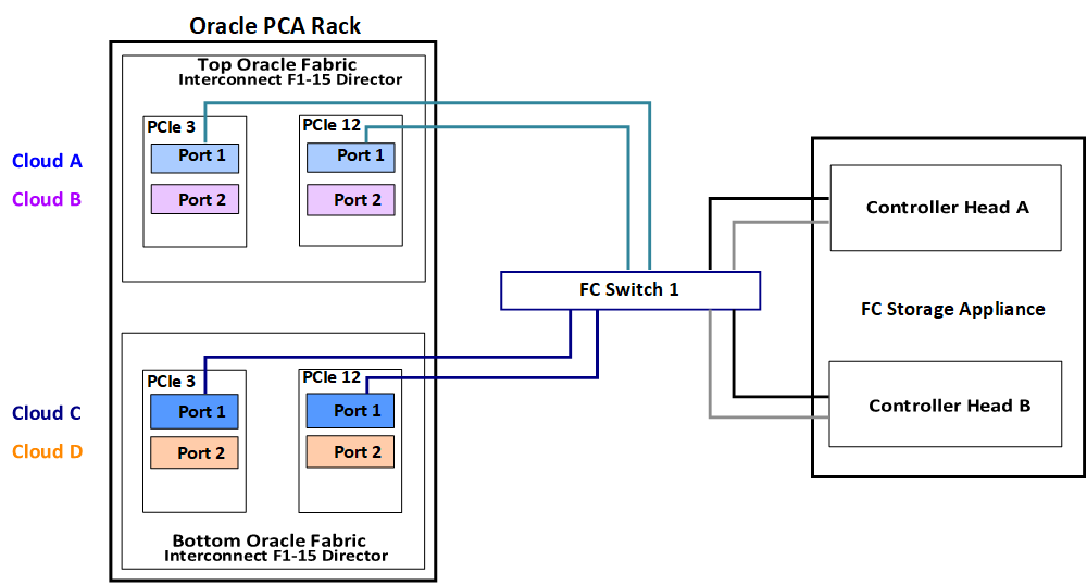
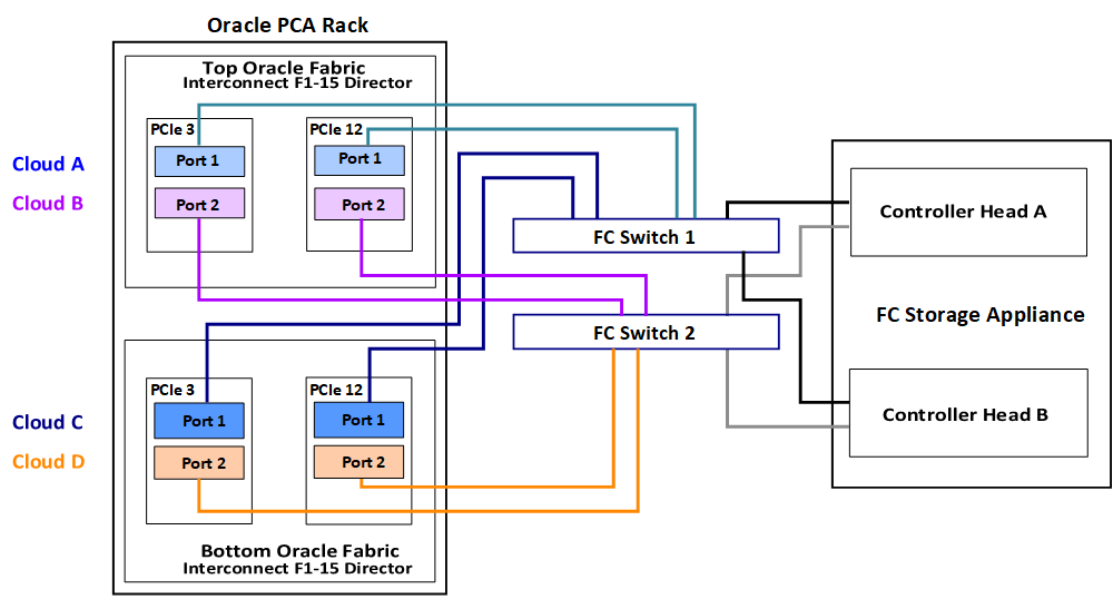
Oracle Private Cloud Appliance introduces the concept of "storage clouds" that group together the FC ports used to connect the Fabric Interconnects to your own FC switch or switches. Two FC ports on each of the Fabric Interconnects are assigned to a cloud. A vHBA is created on each server for each storage cloud. A total of four storage clouds are defined when the Oracle Private Cloud Appliance is provisioned, resulting in four vHBAs on each of the compute and management nodes.
Storage clouds allow you to cable and configure your external storage in such a way as to improve overall throughput or to build a fully HA enabled infrastructure. The storage clouds are created and configured automatically, so that all you need to do is choose the type of HA configuration that you wish to use and then cable accordingly. The design of the storage cloud configuration reduces complexity in configuration and allows the greatest possible flexibility in terms of your HA requirements.
At bare minimum, a single cloud can be used to access storage on each of your compute nodes or on your management nodes. However a simple HA configuration is recommended. To achieve this, you should use at least two clouds cross-cabled from each of the Fabric Interconnects. For a fully HA-enabled environment, you can use all four clouds cross-cabled between the Fabric Interconnects and two of your own FC switches.
If you do not require HA, you can use multiple clouds to increase overall throughput. In this configuration, you can cable three clouds into separate switches and connect them to the same storage. If one cloud should fail, you are able to bring up the fourth cloud to take over its function and to maintain the same level of throughput.
Each of these configurations is achieved entirely through the different ways in which your FC switch or switches are patched into the Fabric Interconnects. These approaches are described in more detail in Section 8.2.2.3, “Connecting Fibre Channel Hardware”.
Since storage clouds map directly to the vHBAs on each server, it is possible to configure zones on your FC switch or switches to securely separate traffic for each storage cloud. This gives you the opportunity to use separate clouds for different purposes using secured channels to facilitate communication between servers and the LUNs on your storage. This is described in Section 8.2.2.4, “Zone Configuration”.
To use Fibre Channel with the Oracle Private Cloud Appliance , you must supply your own NPIV-capable FC switch or switches. It is not possible to simply patch your FC-capable storage directly into the FC ports on the Fabric Interconnects. This is because the Fabric Interconnects use NPIV – Fibre Channel Node Port ID Virtualization – to map the port nodes to the World Wide Node Names (WWNNs) of the vHBAs that are created on each server. Software required to translate WWPNs to WWNNs does not exist on the storage heads of most FC storage devices, so directly attaching the storage device would prevent registration of the WWPNs for the vHBAs available on each server.
8.2.2.1 Creation of Virtual Host Bus Adaptors (vHBAs)
Each server in the Oracle Private Cloud Appliance is connected to the Fabric Interconnects via an InfiniBand (IB) connection. The Fabric Interconnects are capable of translating connections on their Fibre Channel ports to reroute them over these IB connections. To facilitate this, vHBAs must be defined on each server to map to a storage cloud defined on the Fabric Interconnects. The storage cloud that these vHBAs map to, determine which FC ports they relate to on the Fabric Interconnects.
During the initial configuration of the management nodes, each of the storage clouds is configured automatically on the Fabric Interconnects and vHBAs for each cloud are created on each of the management nodes. WWNNs and WWPNs are generated for the vHBAs on the management nodes. When you cable for a storage cloud and connect your storage appliance, you can add these WWPNs to a storage initiator group and export the LUNs that you wish to make available to your management nodes. These disks can then be mounted on the management nodes as needed. Management nodes are configured with vHBAs to allow them to connect to the different storage clouds so that it is possible to use externally connected storage to store backup and log data, if required.
It is important to distinguish between WWNNs and WWPNs. A WWNN is used to identify a device or node such as an HBA, while a WWPN is used to identify a port that is accessible via that same device. Since some devices can have multiple ports, a device may have a single WWNN and multiple WWPNs.
In the case of the vHBAs that are generated on each compute node, there is a single WWNN and a single WWPN for each vHBA. While these may look almost identical, the fourth hexadecimal octet that makes up the WWNN differs. This is illustrated as follows:
|
WWPN |
WWNN |
|---|---|
|
50:01:39:70:00:4F:91:00 |
50:01:39:71:00:4F:91:00 |
When configuring storage initiators and initiator groups, you should ensure that you are configuring these for the WWPN for each vHBA. If you use the WWNN for any vHBA within an initiator group, that initiator group may not function as expected.
Compute nodes are configured similarly, although the process takes place during compute node provisioning, so that compute nodes are configured as they are provisioned. This means that if you add a compute node to the rack, it is automatically configured so that it is ready to access any externally attached storage. Creation and configuration of vHBAs has also been built into the upgrade process, so that external FC storage can be used with existing environments. Once you have cabled for your storage and have configured the initiator groups on your storage, you can view the LUNs that you make available to your compute nodes directly in Oracle VM Manager.
If you purchased an Oracle Private Cloud Appliance with factory-installed Fibre Channel I/O modules, then these processes are entirely automated and do not require any intervention.
If you purchased an Oracle Private Cloud Appliance without Fibre Channel I/O modules, and you need to install the optional modules into the Fabric Interconnects first, then carefully follow the instructions in Section 8.2.2.2, “Installing Optional Fibre Channel I/O Modules”.
8.2.2.2 Installing Optional Fibre Channel I/O Modules
The X5-2 base rack with Oracle Private Cloud Appliance Release 2.0.3 software marks the first configuration that can be ordered with or without fibre channel I/O modules. In an Oracle Private Cloud Appliance without fibre channel connectivity, slots 3 and 12 of the two Fabric Interconnects are empty. As a consequence, the Software Clouds and vHBAs for Fibre Channel connectivity are not created during provisioning.
If you decide to add Fibre Channel connectivity at a later time, you must order and install the optional Fibre Channel I/O modules, upgrade the controller software and configure the necessary storage clouds and vHBAs.
-
If your Oracle Private Cloud Appliance has no factory-installed Fibre Channel I/O modules you must first make sure that the appliance controller software is Release 2.1.1 or newer. The update process typically takes at least 2.5 hours.
For detailed software update instructions, see Updating Oracle Private Cloud Appliance in the Oracle Private Cloud Appliance Administrator's Guide.
-
When the controller software update has completed successfully, install a total of four Fibre Channel I/O modules in slots 3 and 12 of each Oracle Fabric Interconnect F1-15. You can install the new modules without powering down the Fabric Interconnect.
CautionYou must use only slots 3 and 12. Fibre Channel I/O modules installed in other slots are likely to cause future upgrade issues and are therefore not supported within Oracle Private Cloud Appliance.
-
Ensure that the module's component side is facing towards the right edge of the chassis. Also, ensure that the module's top and bottom edges are correctly aligned with the upper and lower tracks at the left edge of each module slot.
-
Secure the module in the slot by tightening the securing screw located at the bottom edge of the module's rear panel.
CautionTighten the screws so that they are lightly snug. If you overtighten the screws they can break.
-
-
When all four Fibre Channel I/O modules have been installed, configure the storage clouds and vHBAs by running the appropriate commands from the Oracle Private Cloud Appliance Command Line Interface (CLI).
-
Configure the vHBAs on both management nodes.
PCA> configure vhbas ovcamn05r1 ovcamn06r1

Compute_Node         Status
------------         ------
ovcamn05r1           Succeeded
ovcamn06r1           Succeeded
----------------
2 rows displayed

Status: Success
-
Verify that the clouds have been configured.
PCA> list storage-network

Network_Name              Description
------------              -----------
Cloud_A                   Default Storage Cloud ru22 port1 - Do not delete or modify
Cloud_B                   Default Storage Cloud ru22 port2 - Do not delete or modify
Cloud_C                   Default Storage Cloud ru15 port1 - Do not delete or modify
Cloud_D                   Default Storage Cloud ru15 port2 - Do not delete or modify
----------------
4 rows displayed

Status: Success
-
If the 4 storage clouds have been configured correctly, configure the vHBAs on all compute nodes.
PCA> configure vhbas ALL

Compute_Node         Status
------------         ------
ovcacn07r1           Succeeded
ovcacn08r1           Succeeded
[...]
ovcacn36r1           Succeeded
ovcacn37r1           Succeeded
----------------
20 rows displayed

Status: Success
These steps provide only an overview of the procedure. For detailed instructions, see Enabling Fibre Channel Connectivity on a Provisioned Appliance in the Troubleshooting chapter of the Oracle Private Cloud Appliance Administrator's Guide.
-
8.2.2.3 Connecting Fibre Channel Hardware
Cabling requirements to attach external FC-capable storage to the Oracle Private Cloud Appliance are very specific due to the grouping of FC ports for storage clouds on the Fabric Interconnects. You must ensure that when cabling for a storage cloud, both ports defined for the storage cloud are cabled into your FC switch. Ideally, you should cable all four FC ports on each of the Fabric Interconnects within the rack for a total of eight cables, at the same time. These should either connect to a single Fibre Channel switch outside of the rack, or should be cross-connected to two Fibre Channel switches outside of the rack to improve redundancy. The following table describes how ports are grouped to create each cloud:
|
Mapping |
Top Oracle Fabric Interconnect F1-15 (RU 22-25): |
Bottom Oracle Fabric Interconnect F1-15 (RU 15-18): |
||
|---|---|---|---|---|
|
Cloud Name |
I/O Module 3 |
I/O Module 12 |
I/O Module 3 |
I/O Module 12 |
|
A |
Port 1 |
Port 1 |
none |
none |
|
B |
Port 2 |
Port 2 |
none |
none |
|
C |
none |
none |
Port 1 |
Port 1 |
|
D |
none |
none |
Port 2 |
Port 2 |
For a bare minimum configuration, you can use two cables to connect your FC switch to cloud A. This would require that you connect cables to the top Fabric Interconnect in the rack, using I/O Module 3 Port 1 and I/O Module 12 Port 1. Connect each controller head on your FC storage appliance to your FC switch. Typically you would use two cables for each controller head.
For a basic HA configuration, you should cable for cloud A and cloud C. This allows you to use both of the Fabric Interconnects in the rack to improve redundancy. This is the recommended default minimum configuration. It is important that cloud A and cloud C are cabled to the same FC switch.
To maximize an HA configuration, by using an additional FC switch, you can cable cloud B and cloud D into the second FC switch. In this situation you should cross-cable the controller heads on your FC storage appliance, so that each controller head is connected to each of your FC switches.
Other cabling possibilities exist, such as the aforementioned configuration where clouds are each connected to independent FC switches to maximize throughput or to achieve physical traffic separation. Usually, in this configuration, one cloud is left disconnected in standby so that in the event that one of the other clouds fails for some reason, it is possible to connect the standby cloud to take over the function of the failed cloud. In this situation, you would need to configure so that the WWPNs for the standby cloud are substituted for the failed cloud in the initiator groups on your storage appliance.
The most important points to remember when cabling are as follows:
-
Clouds are comprised of two equivalent ports on alternate I/O Modules on the same Fabric Interconnect. For instance, cloud A on the top Fabric Interconnect in the rack is comprised of Port 1 on I/O Module 3 and Port 1 on I/O Module 12; while cloud D on the bottom Fabric Interconnect in the rack is comprised of Port 2 on I/O Module 3 and Port 2 on I/O Module 12.
-
Although not required, you should cable both ports that belong to a cloud to provide redundancy and to allow better throughput.
-
Unless you have defined zones that span more than one FC switch, the ports that belong to a cloud must be cabled to connect to the same FC switch.
-
For HA configurations, clouds on alternate Fabric Interconnects should be connected to the same FC switch. For instance, cloud A and cloud C should be connected to the same FC switch; while cloud B and cloud D can be connected to an alternate switch.
You can connect FC cables to the appliance at any time, and no system shutdown is required, allowing you to dynamically add storage or improve redundancy as required.
8.2.2.4 Zone Configuration
The Oracle Private Cloud Appliance requires that Fibre Channel Zoning is configured on the external FC switches to control and limit the amount of traffic on the storage network for efficient LUN discovery and to maximize stability within the environment.
FC Zoning is also used to enhance security by providing an extra layer of traffic separation on the storage network. Even if you are using storage initiator groups to perform LUN masking, it is generally considered good practice to also configure FC zones to limit the exposure of LUNs and unrestricted use of this network medium. Zone configuration is very useful in the situation where the FC switch or switches are shared with other devices apart from the Oracle Private Cloud Appliance.
The Oracle Private Cloud Appliance supports single initiator pWWN zoning, in line with industry best-practice. It is highly recommended that you configure single initiator pWWN zoning for all Fibre Channel connections to the rack. This requires a Fibre Channel switch that supports NPIV.
For all storage clouds that are cable-connected, at least one zone should be configured per WWPN on each compute node. However, multiple zones may be created for each WWPN depending on your cabling. In a setup using all four storage clouds, four zones should exist on the Fibre Channel switch for each compute node. You can obtain a listing of the WWPNs for the compute nodes by running the pca-admin list wwpn-info command.
Using a Fibre Channel storage device with two controller heads in an active/active cluster, and two targets configured for each head, every LUN has 4 storage paths. A storage path is a connection between a target and a storage cloud. Each LUN has two active paths between a storage cloud and the controller head that owns the LUN, and an additional two standby paths between the same storage cloud and the other controller head. If the storage head that owns the LUN should fail, the other storage head takes over and the standby paths become active. This way the storage connectivity for a given cloud remains uninterrupted. To better support failover/failback operations, consider employing a zoning strategy using two zones per storage cloud. This approach involves one zone connecting a given cloud to a target of one controller head, and a second zone connecting that same cloud to a target of the other controller head.
The configuration of Fibre Channel single initiator pWWN zones is not optional. If you had previously attempted to extend your storage using Fibre Channel and did not configure any zones on your FC switch, you should do so now. Furthermore, if you previously configured D,P zones, it is important that you rezone your switches to use single initiator pWWN zones.
Please refer to the documentation of your switch vendor for more information on the configuration steps that you must perform to configure single initiator pWWN zoning.
8.2.2.5 Configuring Your Storage Appliance
Some initial configuration steps may be required on your appliance before you are able to access storage directly within Oracle VM Manager. Typically these steps involve configuring some form of 'LUN masking' achieved by mapping LUNs to particular initiator groups that ultimately define the servers and clouds that have access to each LUN. These steps are outlined as follows:
-
Create the initiators that you intend to use to identify the different servers in each cloud within your storage appliance. This is achieved by registering the World Wide Port Names (WWPNs) that were created for the vHBAs on each server in the Oracle Private Cloud Appliance rack with your appliance and assigning them aliases so that they can be easily identified as belonging to a particular server and cloud. Most appliances should be able to see the WWPNs presented by the Fabric Interconnects and you can use the Oracle Private Cloud Appliance command line interface to identify matching WWPNs and match them with the recommended aliases that you should use when creating each initiator. This is achieved by running the pca-admin list wwpn-info command:
PCA> list wwpn-info

WWPN                      vHBA     Cloud_Name    Server       Type  Alias
----                      ----     ----------    ------       ----  -----
50:01:39:70:00:69:F1:06   vhba01   Cloud_A       ovcacn08r1   CN    ovcacn08r1-Cloud_A
50:01:39:70:00:69:F1:08   vhba01   Cloud_A       ovcacn32r1   CN    ovcacn32r1-Cloud_A
50:01:39:70:00:69:F1:0C   vhba01   Cloud_A       ovcacn30r1   CN    ovcacn30r1-Cloud_A
50:01:39:70:00:69:F1:0A   vhba01   Cloud_A       ovcacn29r1   CN    ovcacn29r1-Cloud_A
50:01:39:70:00:69:F1:07   vhba02   Cloud_B       ovcacn08r1   CN    ovcacn08r1-Cloud_B
50:01:39:70:00:69:F1:09   vhba02   Cloud_B       ovcacn32r1   CN    ovcacn32r1-Cloud_B
50:01:39:70:00:69:F1:0B   vhba02   Cloud_B       ovcacn29r1   CN    ovcacn29r1-Cloud_B
50:01:39:70:00:69:F1:0D   vhba02   Cloud_B       ovcacn30r1   CN    ovcacn30r1-Cloud_B
50:01:39:70:00:6A:11:0A   vhba03   Cloud_C       ovcacn29r1   CN    ovcacn29r1-Cloud_C
50:01:39:70:00:6A:11:0C   vhba03   Cloud_C       ovcacn30r1   CN    ovcacn30r1-Cloud_C
50:01:39:70:00:6A:11:08   vhba03   Cloud_C       ovcacn32r1   CN    ovcacn32r1-Cloud_C
50:01:39:70:00:6A:11:06   vhba03   Cloud_C       ovcacn08r1   CN    ovcacn08r1-Cloud_C
50:01:39:70:00:6A:11:0D   vhba04   Cloud_D       ovcacn30r1   CN    ovcacn30r1-Cloud_D
50:01:39:70:00:6A:11:0B   vhba04   Cloud_D       ovcacn29r1   CN    ovcacn29r1-Cloud_D
50:01:39:70:00:6A:11:09   vhba04   Cloud_D       ovcacn32r1   CN    ovcacn32r1-Cloud_D
50:01:39:70:00:6A:11:07   vhba04   Cloud_D       ovcacn08r1   CN    ovcacn08r1-Cloud_D
-----------------
16 rows displayed

Status: Success
Note the Alias column in the example output. Use the values presented in this column for each matching WWPN when you configure the initiators on your appliance. The Oracle Private Cloud Appliance CLI is discussed in more detail in the section entitled “The Oracle Private Cloud Appliance Command Line Interface (CLI)” in the Oracle Private Cloud Appliance Administrator's Guide.
-
Create initiator groups that define how your storage should be presented to the different compute nodes and virtual machines within your environment. This step is very dependent on your own storage requirements and should be carefully planned for before you start using the storage appliance in conjunction with the Oracle Private Cloud Appliance.
Remember that there is a WWPN for each vHBA on each compute node, representing each storage cloud defined on the Fabric Interconnects. In an HA configuration, you attach the WWPNs for the different storage clouds to the same initiator group. Using this approach, if a storage cloud fails, the LUNs that are exposed for the initiator group are still available to each compute node via an alternate vHBA. Alternatively, you can sacrifice high availability for a more flexible configuration where the WWPN for each vHBA on each compute node is used independently across different initiator groups. This type of configuration may make more sense where you intend to separate out storage for different functions, such as storage that might be provided to virtual machines and storage that might be used for repositories and server related functions.
-
Map LUNs that you have created on your storage appliance to the initiator groups you have just created. You should only map LUNs to the initiator groups that you intend to use for those LUNs. Although remapping LUNs is possible, you should remember that remapping a LUN once it is in use by Oracle VM is not recommended and may cause unexpected behavior within Oracle VM. Therefore, it is important to carefully plan this step around your requirements before proceeding with this configuration.
CautionA maximum of 1024 LUN paths per host applies.
To perform these steps, you should refer to the appropriate documentation for your appliance or contact your vendor for assistance with these steps. An example is provided in Example 8.1, “Configuring an Oracle Storage Appliance ZS3-4” to show you how you can configure an Oracle Storage Appliance ZS3-4 correctly for this purpose.
It is possible to configure an Oracle Storage Appliance ZS3-4 either using the web-based user interface or the command line interface. These instructions presume that you are using the web-based user interface, since the interface shows all of the WWPNs that it can actually detect.
-
Log into the web-based user interface as either root or a user with adequate permissions to create initiator groups and LUNs.
-
Click on the
Configurationlink, then click on theSANlink. IfFibre Channelis not already selected, click on theFibre Channellink. The SAN Summary page is displayed. -
Click on the
+ Initiatorslink as indicated in the image below:Figure 8.3 Click on the+ Initiatorslink.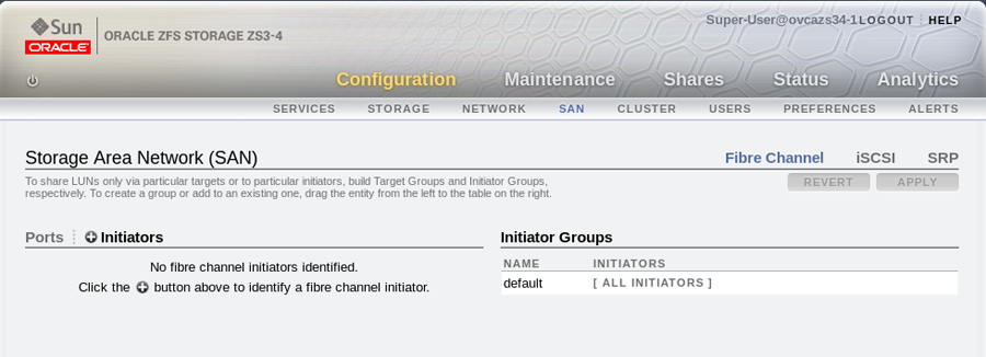
-
The
Identify FC Initiatordialog opens and lists the WWPNs that the ZS3-4 is able to detect. You should create a user-friendly alias for each WWPN listed so that it is easy to identify how these map onto the nodes and clouds configured within the Oracle Private Cloud Appliance. Use the Oracle Private Cloud Appliance command line interface on the active management node to obtain a listing of all of these WWPNs and the recommended aliases that you should use. You can do this by running the pca-admin list wwpn-info command. Find the matching WWPN in theIdentify FC Initiatordialog and click on it to enter the recommended alias in the Alias field. Repeat this action for every WWPN. This step is illustrated in the figure below:Figure 8.4 Use theIdentify FC Initiatordialog to define user-friendly aliases for the WWPNs.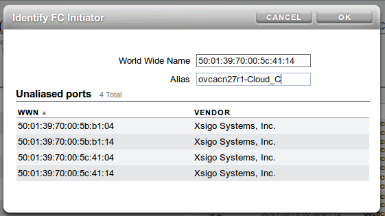
-
When you have finished creating aliases for each WWPN, you can start to create the storage initiator groups where LUNs are presented later in the configuration. To create a new storage initiator group in the SAN Summary view, move your mouse over the left hand side of the WWN name until you see the
moveicon appear, then drag it to the right hand side of the screen and drop it in theCreate New Initiator Groupbox that appears. This step is illustrated in the figure below:Figure 8.5 Use theSAN Summarypage to create a new storage initiator group by dragging an initiator across the page.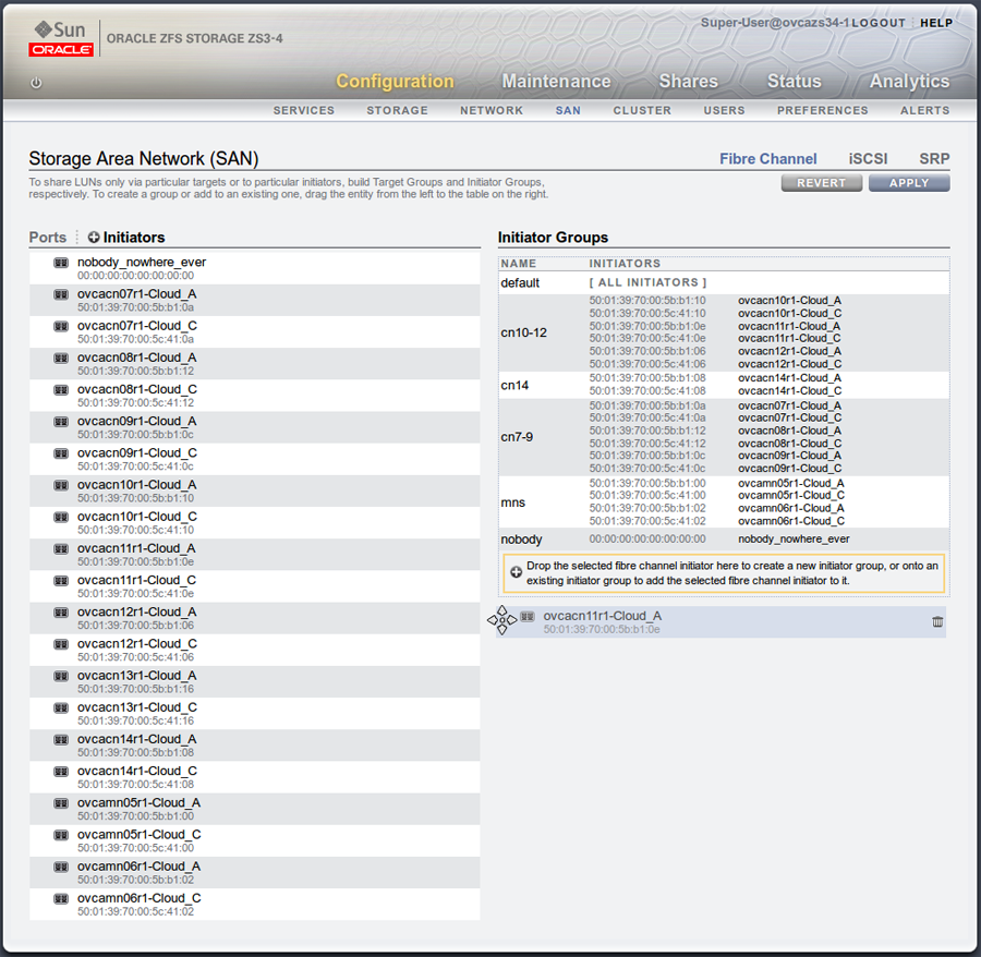
You can create as many initiator groups as you like. In most cases, if your storage is not used outside of the Oracle Private Cloud Appliance and you do not need to segregate storage within the Oracle Private Cloud Appliance, you can simply use the default initiator group. However, if your storage is shared with appliances outside of the Oracle Private Cloud Appliance, you must, at least create an initiator group for all of the initiators that belong to nodes within the Oracle Private Cloud Appliance. If you need to segregate storage further, you can create initiator groups that only include the initiators for particular compute nodes, as is illustrated in the screenshot.
-
Once you have created a new initiator group, you can roll over it using your mouse and then click on the edit icon that appears in the form of a pencil. A dialog appears where you are able to edit the initiator name to change it to something more appropriate. You can also select the rest of the initiators that you wish to include in the initiator group. Click when you have finished editing the initiator group.
-
When you have finished creating and editing initiator groups, it is important that you click on the button on the SAN Summary page to save the changes that you have made.
-
You can now define how LUNs map to your initiator groups depending on your requirements. This is achieved by clicking on the
Shareslink in the navigation bar at the top of the page. On theProject Summarypage, you can view any storage pools that you have defined and the LUNs associated with those pools. You can also create new LUNs for each storage pool as required. On this page, you can click to edit a LUN and edit the storage initiator groups that it is exposed to. In this view, you can make a LUN accessible to any of the storage initiators that you defined in the previous steps.
8.2.2.6 Updating Physical Disks in Oracle VM Manager
Since vHBAs are created on each compute node during the provisioning or upgrade process, the storage should be automatically refreshed within Oracle VM Manager as part of this process and the physical disks should be visible within Oracle VM Manager immediately. However, in the case that a disk is not displayed within Oracle VM Manager after the initial server discovery is performed, it is possible that you may need to rediscover the compute nodes so that Oracle VM Manager sees the vHBAs and the LUNs that are accessible to them. The following steps describe actions that should be performed in Oracle VM Manager to start making use of your newly attached FC storage in the case where these disks do not appear automatically within Oracle VM Manager.
Reprovisioning restores a compute node to a clean state. If a compute node with active connections to external storage repositories is reprovisioned, the external storage connections need to be configured again after reprovisioning.
-
Log into the Oracle VM Manager web-interface on the Oracle Private Cloud Appliance.
-
Click on the
Servers and VMstab and select all of your compute node servers. -
Click on the
Rediscover Serversicon to rediscover all of your servers. -
After you have finished rediscovery, check that there are four new vHBAs for each server by clicking on the server in the navigation pane and then changing the perspective to
Storage Initiators. -
Click on the
Storagetab. -
Expand the
SAN Serversitem in the navigation pane and select theUnmanaged Fibre Channel Storage Array. -
Click on the
Editicon and navigate to theAdmin Serverstab in the dialog that appears. -
Add all of the compute node servers as admin servers for the storage array and click to close the dialog.
-
Click on the
Refresh SAN Servericon and click on the confirmation dialog. -
Wait for all of your servers to be updated. This operation can take several minutes to complete.
-
The LUNs display in the
Physical Disksperspective for theUnmanaged Fibre Channel Storage Array. -
You can check that the LUNs are also available to your servers on the
Servers and VMstab by clicking on a server and changing the perspective to thePhysical Disksview.
8.2.3 Adding External InfiniBand Storage
InfiniBand can be used to connect additional ZFS Storage Appliances to the Oracle Private Cloud Appliance (PCA) using the available ports on the Fabric Interconnects. Since ZFS Storage Appliances are dual-headed, each ZFS Controller head has its own InfiniBand connection to each of the Fabric Interconnects, providing redundancy both on the side of the ZFS Storage Appliance and on the side of the Oracle Private Cloud Appliance.
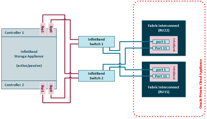
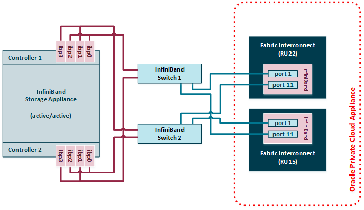
The Oracle Fabric Interconnect F1-15s have only 4 available InfiniBand ports – 2 per Fabric Interconnect – to attach external storage. If higher performance is required, or if multiple storage appliances need to be connected, you may add two external NM2-36P Sun Datacenter InfiniBand Expansion Switches between the external storage and the Fabric Interconnects inside the appliance rack. A ZFS Storage Appliance may be connected to the InfiniBand Switches in active/passive or active/active configuration. If an active/active configuration is selected, then both storage controllers must be expanded with additional HCAs for a total of 4 InfiniBand ports per ZFS controller head.
For the latest, detailed information about InfiniBand storage with Oracle Private Cloud Appliance, please refer to the technical paper entitled Expanding Oracle Private Cloud Appliance Using Oracle ZFS Storage Appliance.
8.2.3.1 Connecting InfiniBand Storage Hardware
The recommended cabling configuration that should be implemented to connect the ZFS appliance to the Oracle Private Cloud Appliance cross-connects each controller head to each of the Fabric Interconnects for a total of four connections. This configuration maximizes redundancy and throughput. The following table describes how the cabling should be connected between the Fabric Interconnects on the Oracle Private Cloud Appliance and the ZFS Storage Appliance.
|
Top Oracle Fabric Interconnect F1-15 (RU 22-25): |
Bottom Oracle Fabric Interconnect F1-15 (RU 15-18): |
ZFS Storage Appliance Controller Head 1 |
ZFS Storage Appliance Controller Head 2 |
|---|---|---|---|
|
IB Port 1 |
none |
IB Port 1 (ibp0) |
none |
|
IB Port 11 |
none |
none |
IB Port 1 (ibp0) |
|
none |
IB Port 1 |
IB Port 2 (ibp1) |
none |
|
none |
IB Port 11 |
none |
IB Port 2 (ibp1) |
If you install two InfiniBand switches between the external storage and the appliance rack, then those switches connect to the Fabric Interconnect ports using the same cabling pattern as the two controllers of a directly attached ZFS Storage Appliance. On the side of the ZFS Storage Appliance, the cabling pattern in active/passive configuration remains identical whether it is connected to the InfiniBand switches or directly to the Fabric Interconnects.
If the ZFS Storage Appliance is in active/active configuration, the cable connections must be doubled to provide redundancy between both ZFS controllers and the pair of InfiniBand switches. Because both controller heads are in active mode, they both require redundant connections to the two switches, meaning 4 cables per controller.
The different supported cabling layouts are illustrated in the figures below.
8.2.3.2 IP Address Allocation
The following IP address blocks have been reserved for use by a ZFS Storage Appliance external to the Oracle Private Cloud Appliance rack:
-
192.168.40.242
-
192.168.40.243
-
192.168.40.244
-
192.168.40.245
-
192.168.40.246
-
192.168.40.247
-
192.168.40.248
-
192.168.40.249
8.2.3.3 Configuring the ZFS Storage Appliance
This section describes the configuration steps that you must perform on the ZFS Storage Appliance to use IPoIB in conjunction with the Oracle Private Cloud Appliance. The description provided here assumes a typical configuration with an active/passive management cluster, using iSCSI to serve LUNs to compute nodes or virtual machines as physical disks. The ZFS Storage Appliance supports a standard NFS configuration as well.
If you install extra expansion cards in the ZFS Storage Appliance controllers, and add a pair of InfiniBand switches between the external storage and the Fabric Interconnects inside the appliance rack, you can set up the ZFS Storage Appliance management cluster in active/active configuration. Notes in the procedure below highlight the required additional configuration.
-
Create Datalinks
Log on to management user interface on the controller head you intend to use as the active node. Go to and then to . If you have cabled correctly, two active devices are listed that map onto the cabled IB ports.
NoteIn active/active configuration both controller heads have 4 active devices: typically
ibp0,ibp1,ibp2andibp3.Drag each of these across to the Datalink menu to create a new datalink for each device. Edit each of these datalinks to provide a datalink name and partition key.
Figure 8.9 Datalink Configuration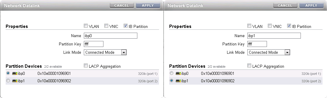
-
Create Interfaces
Drag each configured datalink across into the Interface menu to create an interface for each datalink that you have defined. Edit each interface to provide a value for the Name field that makes it easy to identify the interface. Add the netmask 0.0.0.0/8 to each interface to prevent the system from probing and testing the routing details behind the network connection. Leave the IP MultiPathing Group unchecked. Do not configure an IP address at this stage.
Figure 8.10 Interface Configuration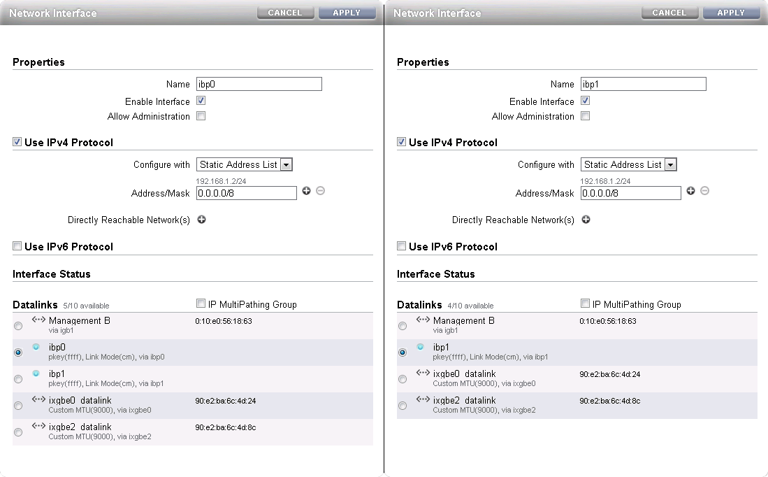
-
Configure Multipathing
Click the Plus icon in the Interface menu to create an additional interface. This additional interface enables IPMP across the two interfaces you created in the previous step. Enter a value in the Name field that makes it easy to identify the IPMP interface. Assign an IP address from the list of reserved IPs in the Oracle Private Cloud Appliance storage network.
Near the bottom of the window, select the IP MultiPathing Group check box. Select the two previously configured interfaces, mark the first one as Active and the second one as Standby. The selected IP address will be configured on the active interface until a failover to the standby interface occurs.
NoteIn active/active configuration you create 2 IPMP interfaces: one across interfaces
ibp0andibp2, and the other acrossibp1andibp3. This ensures redundancy across the two PCIe InfiniBand expansion cards. Assign an IP address to each IPMP interface. The configuration is replicated to the other storage controller.Figure 8.11 Multipathing (IPMP) Configuration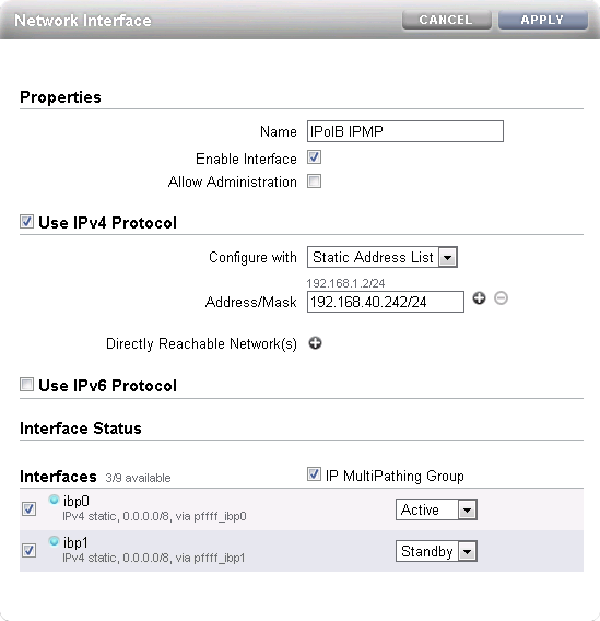
-
Apply Connectivity Configuration
Click the Apply button to commit the connectivity configuration you performed up to this point. When you select any device, datalink or interface associated with your configuration, all related items are highlighted in the user interface, as shown in the screenshot below. All other items unrelated to the configuration in this procedure have been blurred out in the image.
Figure 8.12 Final Connectivity Configuration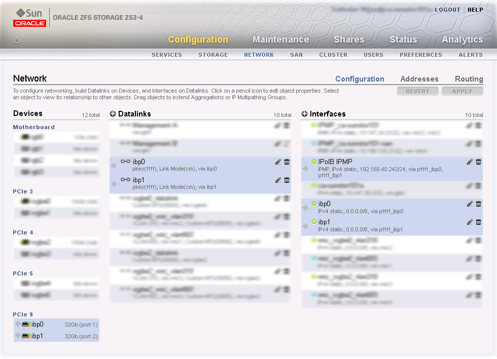
-
Verify Management Cluster Configuration
The external storage setup proposed in this chapter has an active/passive cluster configuration. Consequently all storage resources for Oracle Private Cloud Appliance have to be available at one particular IP address at any time. The IP address and the storage resources are owned by the active head in the management cluster, and the standby head is ready to take over the IP address and expose the same storage resources if the active head should fail.
On the active storage controller, go to and then to . The active/passive cluster configuration is illustrated in the screenshot below. All resources involved in the Oracle Private Cloud Appliance external storage setup are owned by the active head: the storage appliance management interface, the IPMP interface configured specifically for Oracle Private Cloud Appliance external storage connectivity, and the storage pool where the LUNs will be created.
In this setup the entire configuration is applied on the active controller and automatically replicated on the standby controller. Since all resources are owned by the active head, there is no need to log on to the standby head and make any configuration changes.
NoteIn active/active configuration both storage controllers take ownership of the storage resources in their storage pool. Each storage controller presents its storage resources to Oracle Private Cloud Appliance using separate redundant network paths. The active path at any given moment is determined through multipathing.
Figure 8.13 Management Cluster Configuration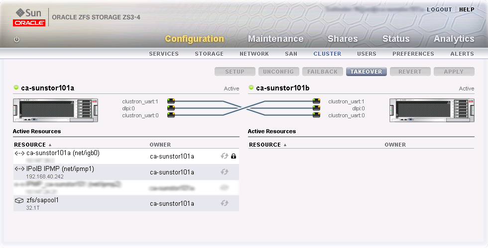
-
Configure iSCSI Targets
On the active controller, go to , and then to . Click the Plus icon in the Targets menu to create a new iSCSI target. Enter a value in the Alias field that makes it easy to identify the iSCSI target. Select the IPMP interface you configured specifically for Oracle Private Cloud Appliance external storage connectivity. Click OK to create the new target.
Figure 8.14 Create iSCSI Target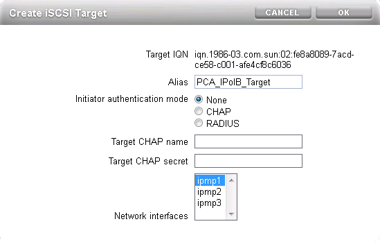
Drag the iSCSI target that you have created into the Target Group area to create a target group. Edit the target group, give it an appropriate name, and make sure the IQN of the correct iSCSI target is selected. Click OK to save your changes.
Figure 8.15 Create iSCSI Target Group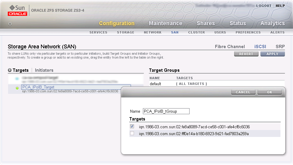
NoteIn active/active configuration you must create an iSCSI target and target group on each storage controller. In the target configuration select the two IPMP interfaces you created.
The iSCSI initiators and initiator group, which are configured in the steps below, are automatically replicated to the second storage controller.
-
Configure iSCSI Initiators
First, you need to retrieve the IQN of each compute node you wish to grant access to the external storage. Log on to the active management node of your Oracle Private Cloud Appliance and proceed as follows:
-
Using the CLI, list all compute nodes.
[root@ovcamn05r1 ~]# pca-admin list compute-node

Compute_Node  IP_Address    Provisioning_Status  ILOM_MAC            Provisioning_State
------------  ----------    -------------------  --------            ------------------
ovcacn09r1    192.168.4.7   RUNNING              00:10:e0:3f:82:75   running
ovcacn13r1    192.168.4.11  RUNNING              00:10:e0:3f:87:73   running
ovcacn26r1    192.168.4.13  RUNNING              00:10:e0:3e:46:db   running
ovcacn12r1    192.168.4.10  RUNNING              00:10:e0:3f:8a:c7   running
ovcacn08r1    192.168.4.6   RUNNING              00:10:e0:3f:84:df   running
ovcacn27r1    192.168.4.14  RUNNING              00:10:e0:3f:9f:13   running
ovcacn07r1    192.168.4.5   RUNNING              00:10:e0:3f:75:73   running
ovcacn11r1    192.168.4.9   RUNNING              00:10:e0:3f:83:23   running
ovcacn10r1    192.168.4.8   RUNNING              00:10:e0:3f:89:83   running
ovcacn14r1    192.168.4.12  RUNNING              00:10:e0:3f:8b:5d   running
-----------------
10 rows displayed

Status: Success
-
SSH into each compute node and display the contents of the file
initiatorname.iscsi.[root@ovcamn05r1 ~]# ssh ovcacn07r1 root@ovcacn07r1's password: [root@ovcacn07r1 ~]# cat /etc/iscsi/initiatorname.iscsi InitiatorName=iqn.1988-12.com.oracle:a72be49151 [root@ovcacn07r1 ~]# exit logout Connection to ovcacn07r1 closed. [root@ovcamn05r1 ~]#
TipUsing SSH to connect to each of the listed compute nodes is the fastest way to obtain the IQNs. However, they can also be copied from the Oracle VM Manager user interface, in the Storage Initiator perspective for each server.
-
Copy the IQN of the compute node and use it to define a corresponding iSCSI initiator in the ZFS Storage Appliance user interface.
Click on the Initiators link to define the iSCSI initiators for the compute nodes that you wish to expose LUNs to. Click the Plus icon to identify a new iSCSI initiator. Enter the compute node Initiator IQN and an Alias that makes it easy to identify the iSCSI initiator. Repeat this for each compute node so that all initiators appear in the list.
Figure 8.16 Identify iSCSI Initiators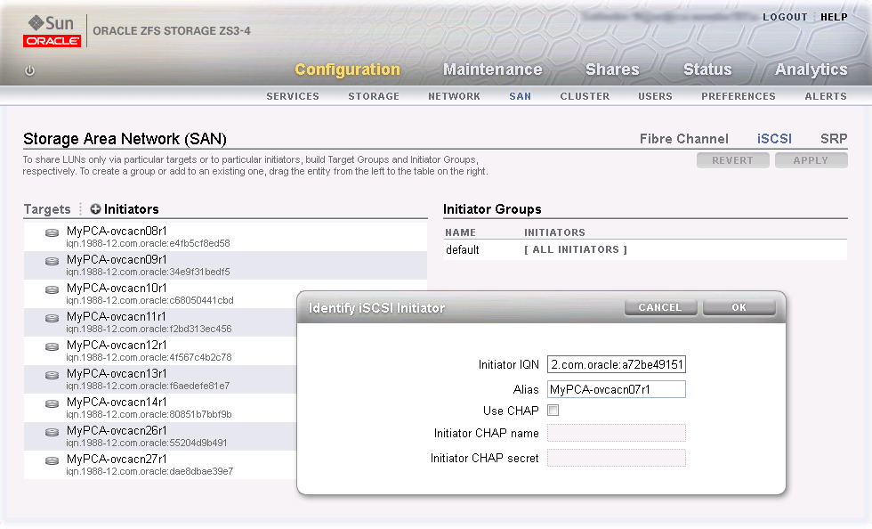
Drag the one of the iSCSI initiators that you have created into the Initiator Group area to create a new initiator group. Edit the initiator group, give it an appropriate name, and make sure that all IQNs of the compute nodes that you want to make a member of this initiator group are selected. Click OK to save your changes.
Figure 8.17 Create iSCSI Initiator Group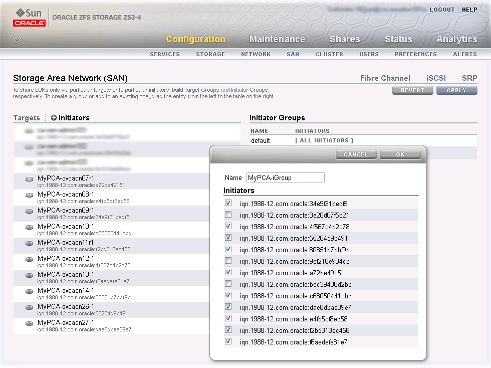
-
-
Apply iSCSI Target and Initiator Configuration
Click the Apply button to commit the iSCSI target and initiator configuration you performed up to this point. When you select any initiator or initiator group associated with your configuration, all related items are highlighted in the user interface, as shown in the screenshot below. Other items unrelated to the configuration in this procedure have been blurred out in the image.
Figure 8.18 Final iSCSI Configuration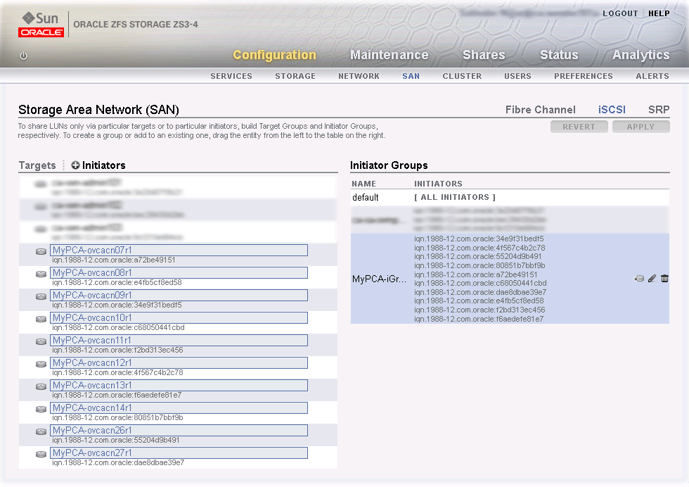
-
Create a LUN
For easy management it is good practice to organize storage resources in separate projects. Create a project first for your Oracle Private Cloud Appliance external storage, and then add LUNs as you need them.
On the active storage controller, go to . On the left hand side, click the Plus icon to create a new Project. In the Create Project dialog box, enter a Name to make it easy to identify the project. Click Apply to save the new project.
Figure 8.19 Create ZFS Storage Project
In the navigation pane on the left hand side, select the project you just created. In the Shares window, first select LUNs,and then click the Plus icon to create a new LUN as part of this project.
Fill out the LUN properties, select the iSCSI target group and initiator group you created earlier, and enter a Name that makes it easy to identify the LUN. Click Apply to add the LUN to the selected project.
Figure 8.20 Create LUN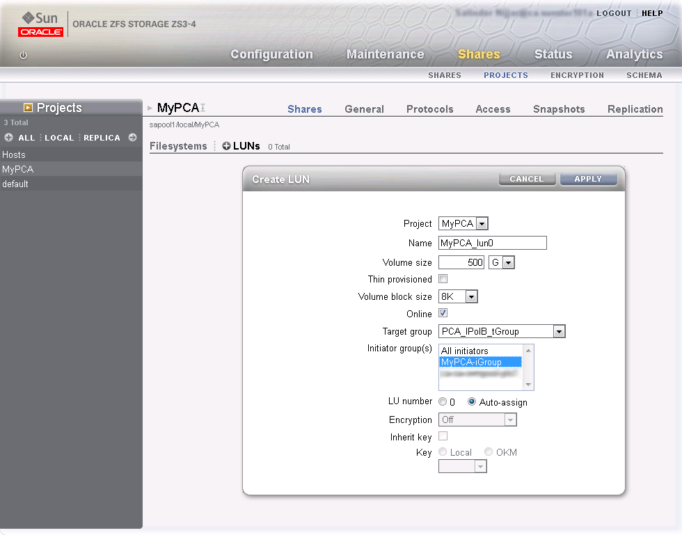
NoteIn active/active configuration each storage controller owns a storage pool. You must create a storage project for use with Oracle Private Cloud Appliance on each storage controller. Associate the LUNs you create with the iSCSI initiator group containing the Oracle Private Cloud Appliance compute nodes, and with the iSCSI target group of the selected storage controller. As a result, the LUNs in question are owned by that storage controller. For optimal performance the ownership of storage resources should be balanced between both active storage controllers.
If you wish to access these LUNs as physical disks within Oracle VM Manager, you must configure Oracle VM Manager first. Refer to ISCSI Configuration for more information.
8.2.3.4 Enabling External IPoIB Storage in Oracle VM Manager
If you intend to use your ZFS appliance to provide storage for use directly by Oracle VM, to host repositories and virtual machines, you must configure the storage within Oracle VM Manager before you are able to use it. The configuration steps that you must perform depend on whether you have configured iSCSI or NFS on your ZFS Storage Appliance. This section provides a brief outline of the steps that you must perform to configure Oracle VM Manager for each of these technologies. For more detailed information, you should refer to the Oracle VM documentation.
If you only intend to make this storage available to individual virtual machines and do not intend to use the storage for underlying Oracle VM infrastructure, you do not need to perform any of the steps documented in this section, but you will need to configure each virtual machine directly to access the storage either over NFS or iSCSI.
Reprovisioning restores a compute node to a clean state. If a compute node with active connections to external storage repositories is reprovisioned, the external storage connections need to be configured again after reprovisioning.
ISCSI Configuration
The following configuration steps should be performed in Oracle VM Manager if you have configured your storage appliance for iSCSI. The process to add a SAN Server in Oracle VM Manager is clearly documented in the Oracle VM Manager User's Guide. Refer to the section entitled Discover SAN Server.
-
Log into Oracle VM Manager on the Oracle Private Cloud Appliance
-
Select the
Storagetab to configure your storage -
Click on the
Discover SAN Servericon to load the wizard -
Enter the DNS name of the storage appliance in the Name field. In the Storage Type field, use the drop-down selector to select
iSCSI Storage
                Server
. In the Storage Plug-in field, you must select theOracle Generic SCSI plugin. Note that alternate storage plugins are not supported in this configuration. Click .Figure 8.21 Discover the SAN Server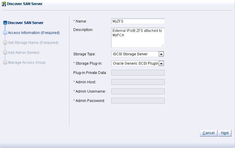
-
In the Access Information dialog, click on the icon that allows you to add a new Access Host. This opens the Create Access Host dialog. Enter the IP address that you configured for the IPMP interface of the storage appliance, for example 192.168.40.242. If you have configured your storage appliance with CHAP access, you must also enter the CHAP username and password here. Click to close the Create Access Host dialog. Click .
Figure 8.22 Create Access Host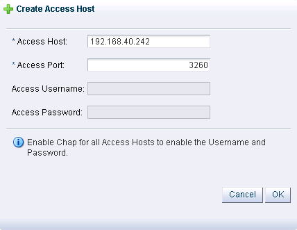
-
In the Add Admin Servers dialog, select all of the servers in the Available Servers frame and move them to the Selected Servers frame. Click .
-
In the Manage Access Group dialog, click on
Default Access Groupand then click on the Edit icon. The Edit Access Group dialog is opened. Click on theStorage Initiatorstab. Select the IQN name from all of the initiators that you have configured on the ZFS Storage Appliance and move them into the Selected Storage Initiators pane. Usually it is acceptable to move all of the IQNs across. Click to save the changes.Figure 8.23 Edit Access Group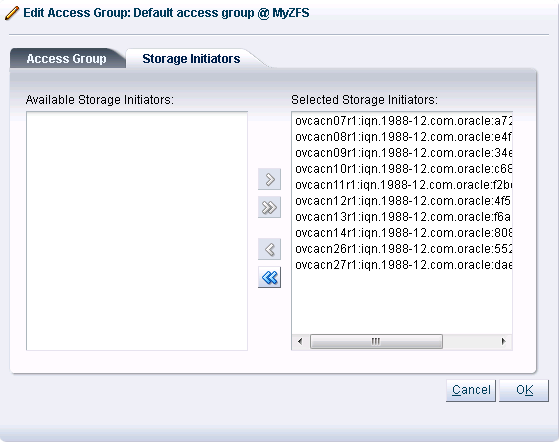
-
Click the button to exit the wizard and to save your changes.
The iSCSI server appears in the SAN Servers tree in the navigation pane. After storage discovery the LUN appears in the Physical Disks perspective.
Figure 8.24 New Physical Disk Available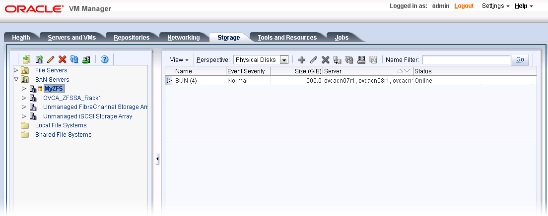
-
If the ZFS Storage Appliance is running in active/active configuration, the two exposed iSCSI targets are detected as separate SAN servers by Oracle VM Manager. You must execute the Discover SAN Server procedure separately for each access host IP address, so that the storage resources owned by each of the two respective controllers are available for use with Oracle Private Cloud Appliance.
NFS Configuration
The following configuration steps should be performed in Oracle VM Manager if you have configured your storage appliance for NFS. The process to add a File Server in Oracle VM Manager is clearly documented in the Oracle VM Manager User's Guide. Refer to the section entitled Discover File Server.
-
Log into Oracle VM Manager on the Oracle Private Cloud Appliance
-
Select the
Storagetab to configure your storage -
Click on the
Discover File Servericon to load the wizard -
Enter all required information into the wizard. Use the IP addresses that you configured for the device as the Access Host IP, for example 192.168.40.242.
-
Select all of the compute nodes that should be designated as Admin Servers.
-
Select two or three compute nodes that should be used as Refresh Servers.
-
Select the file systems that you would like to use.
-
Click the
Finishbutton. -
The file server appears in the File Servers tree in the navigation pane.
-
If the ZFS Storage Appliance is running in active/active configuration, you must execute the Discover File Server procedure separately for each access host IP address, so that the storage resources owned by each of the two respective controllers are available for use with Oracle Private Cloud Appliance.