JavaScript is required to for searching.
Skip Navigation Links
Exit Print View
Sun Datacenter InfiniBand Switch 36 Topic Set
search filter icon
search icon

Document Information

Using This Documentation

Related Documentation

Documentation, Support, and Training

User's Guide

Installing the Switch

Understanding Switch Specifications

Physical Specifications

Environmental Requirements

Acoustic Noise Emissions

Electrical Specifications

Network Management Connector and Pins

USB Management Connector and Pins

QSFP Connector and Pins

Routing Service Cables

Power Cord Requirements

Management Cable Requirements

Understanding InfiniBand Cabling

InfiniBand Cable Cautions

InfiniBand Cable Guidelines

InfiniBand Cable Types

InfiniBand Cable Path Lengths

InfiniBand Cable Bundling

Floor and Underfloor Delivery of InfiniBand Cables

Overhead Delivery of InfiniBand Cables

Preparing for Installation

Installation Preparation

Suggested Tools

Antistatic Precautions

Installation Responsibilities

Installation Sequence

Verify Shipping Carton Contents

Route the InfiniBand Cables

Install the Switch in the Rack

Powering On the Switch

Attach the Management Cables

Attach the Power Cords

Accessing the Management Controller

Access the Management Controller From the Network Management Port

Access the Management Controller From the USB Management Port

Verify the Switch Status

Start the Subnet Manager

Connecting InfiniBand Cables

Attach the InfiniBand Cables

Check Link Status

Verifying the InfiniBand Fabric

Discover the InfiniBand Fabric Topology

Perform Diagnostics on the InfiniBand Fabric

Validate the InfiniBand Fabric and Report Errors

Administering the Switch

Troubleshooting the Switch

Understanding Administrative Commands

Monitoring the Hardware

Monitoring the InfiniBand Fabric

Monitoring the Subnet Manager

Controlling the Hardware

Controlling the InfiniBand Fabric

Controlling the Subnet Manager

Servicing the Switch

Replaceable Components

Servicing Power Supplies

Servicing Fans

Servicing InfiniBand Cables

Servicing the Battery

Firmware Upgrades

Remote Management

Understanding Oracle ILOM on the Switch

Oracle ILOM Overview

Supported Features

Understanding Oracle ILOM Targets

Installing the Oracle ILOM Firmware

Firmware Delivery

Acquire the Oracle ILOM Firmware Version 1.1.3

Install the Oracle ILOM Firmware Version 1.1.3

Administering Oracle ILOM (CLI)

CLI Overview

Accessing Oracle ILOM From the CLI

Switching Between the Oracle ILOM Shell and the Linux Shell

Monitoring Oracle ILOM Targets (CLI)

Controlling Oracle ILOM Targets (CLI)

Upgrading the Switch Firmware Through Oracle ILOM (CLI)

Administering Oracle ILOM (Web)

Web Interface Overview

Access Oracle ILOM From the Web Interface

Monitoring Oracle ILOM Targets (Web)

Controlling Oracle ILOM Targets (Web)

Upgrading the Switch Firmware Through Oracle ILOM (Web)

Using the Fabric Monitor

Access the Fabric Monitor

Fabric Monitor Features

Accessing the Rear Panel Diagram

Accessing Status Pane Information

Control Panel Function

Monitoring Parameters and Status

Administering Oracle ILOM (SNMP)

SNMP Overview

Understanding SNMP Commands

Monitoring Oracle ILOM Targets (SNMP)

Controlling Oracle ILOM Targets (SNMP)

Administering Hardware (IPMI)

ipmitool Overview

Display the Sensors' State (IPMI)

Display the Sensor Information (IPMI)

Display the System Event Log (IPMI)

Display FRU ID Information (IPMI)

Display Switch Status LED States (IPMI)

Enable the Locator LED (IPMI)

Disable the Locator LED (IPMI)

Understanding Oracle ILOM Commands

cd Command

create Command

delete Command

dump Command

exit Command (ILOM)

help Command (ILOM)

load Command

reset Command

set Command

show Command

version Command (ILOM)

Reference

Understanding Hardware Commands

Linux Shells for Hardware Commands

chassis_led Command

checkboot Command

checkguidfilesftree Command

checkpower Command

checktopomax Command

checkvoltages Command

connector Command

dcsport Command

disablecablelog Command

disablelinklog Command

disablesm Command

disableswitchport Command

enablecablelog Command

enablelinklog Command

enablesm Command

enableswitchport Command

env_test Command

exit Command (Hardware)

generatetopology Command

getfanspeed Command

getmaster Command

getnm2type Command

getportstatus Command

help Command (Hardware)

ibdevreset Command

listlinkup Command

managementreset Command

matchtopology Command

setcontrolledhandover Command

setloghost Command

setmsmlocationmonitor Command

setsmpriority Command

setsubnetprefix Command

showfruinfo Command

showpsufru Command

showsmlog Command

showtemps Command

showtopology Command

showunhealthy Command

smconfigtest Command

version Command (Hardware)

Understanding InfiniBand Commands

Linux Shells for InfiniBand Commands

ibaddr Command

ibcheckerrors Command

ibchecknet Command

ibchecknode Command

ibcheckport Command

ibcheckportstate Command

ibcheckportwidth Command

ibcheckstate Command

ibcheckwidth Command

ibclearcounters Command

ibclearerrors Command

ibdatacounters Command

ibdatacounts Command

ibdiagnet Command

ibdiagpath Command

ibhosts Command

ibnetdiscover Command

ibnetstatus Command

ibnodes Command

ibportstate Command

ibroute Command

ibrouters Command

ibstat Command

ibstatus Command

ibswitches Command

ibsysstat Command

ibtracert Command

perfquery Command

saquery Command

sminfo Command

smpdump Command

smpquery Command

Understanding SNMP MIB OIDs

OID Tables Overview

Understanding the SUN-DCS-MIB MIB OIDs

SUN-HW-TRAP-MIB MIB OIDs

Understanding the SUN-ILOM-CONTROL-MIB MIB OIDs

Understanding the SUN-PLATFORM-MIB MIB OIDs

Understanding the ENTITY-MIB MIB OIDs

Index

Attach the InfiniBand Cables


Caution

Caution - InfiniBand cables must never turn tighter than a 5-inch (127 mm) radius. A tighter radius damages the wires and fibers inside the cable.


Note - When you install the InfiniBand cables, connect cables to the lower connectors first. Then connect cables to the upper connectors.
  1. Identify the prerequisite and subsequent installation tasks that you must perform in conjunction with this procedure.

    See Installation Sequence.

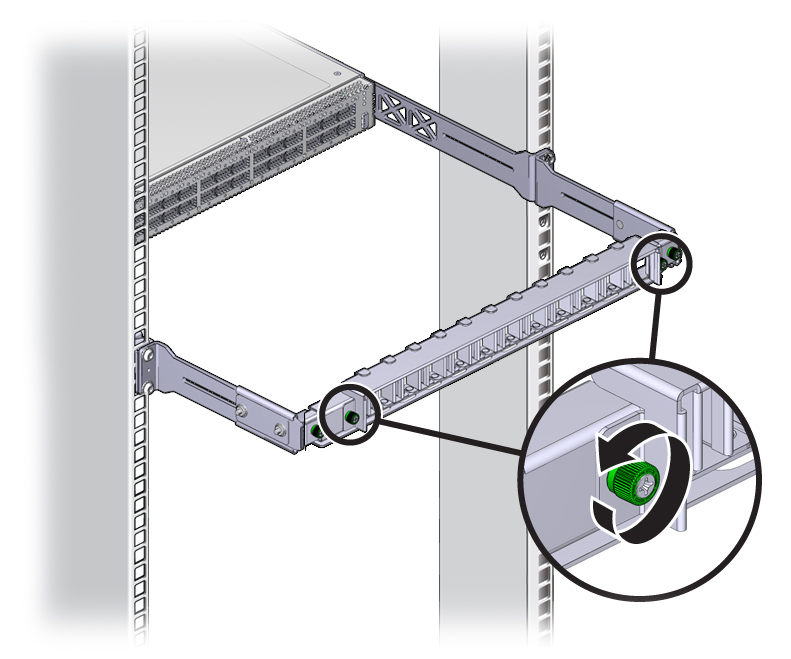
  2. Loosen the two captive thumbscrews that secure the cover to the cable management bracket.
    Illustration shows the thumbscrew being loosened.
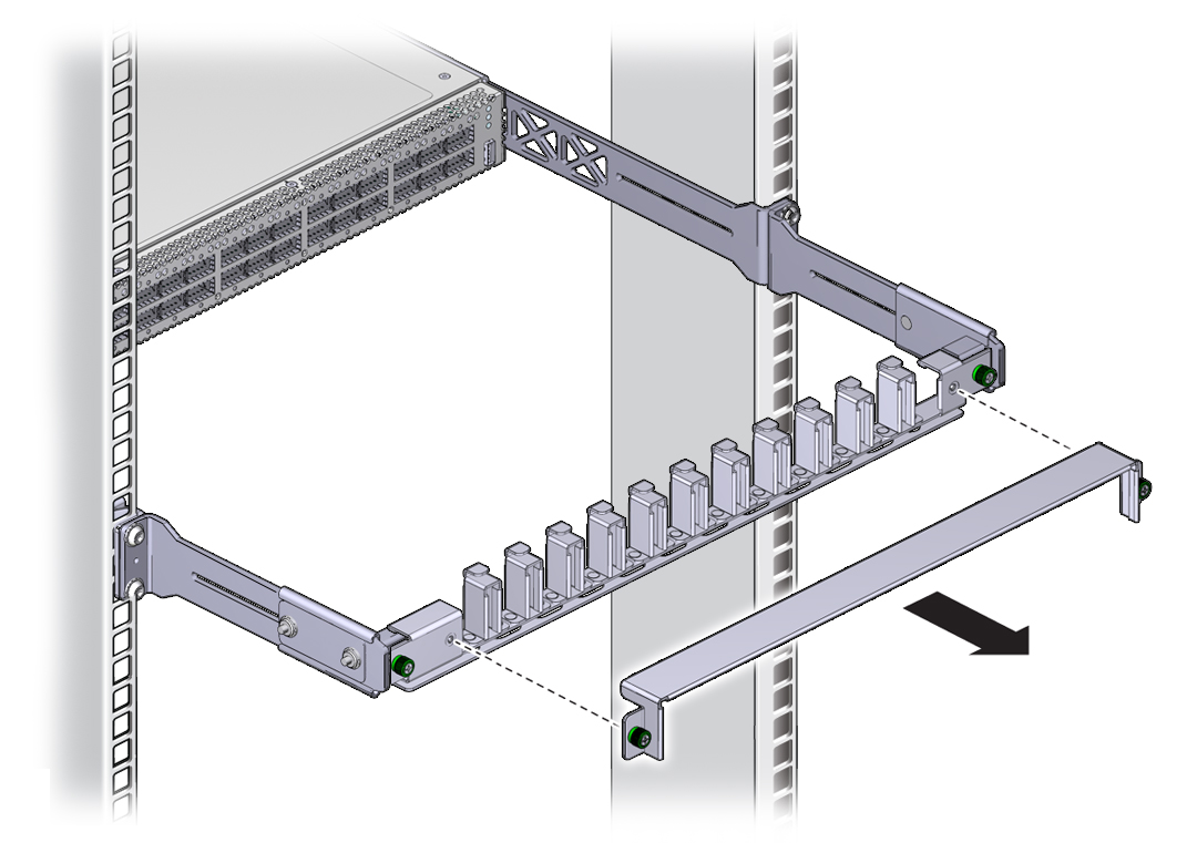
  3. Lift the cover off.
    Illustration shows the cable management bracket cover being removed.
  4. Remove the protective cap from the connector and visually inspect the cable connector.

    The shell should not be bent and should be parallel to the inner boards. If the connector is bent or damaged, use a different cable.

  5. Ensure that the retraction strap is folded back against the cable.
  6. Orient the cable connector to the QSFP receptacle squarely and horizontally.

    Ensure that the L groove is up for the top row of receptacles, or that the L groove is down for the bottom row of receptacles.
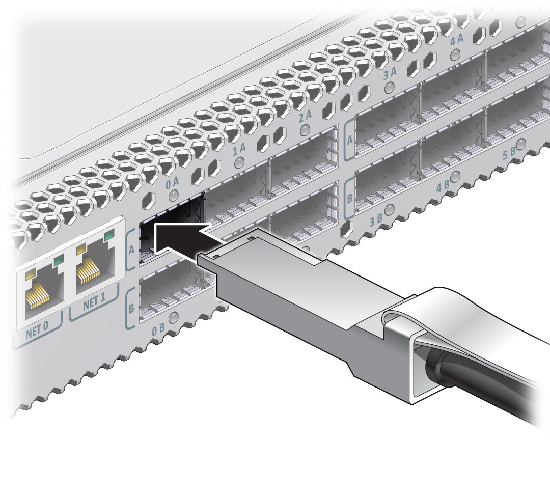

    Illustration shows the InfiniBand cable being attached.

    Note - On some QSFP cable connectors, there is a retraction strap. Both the retraction strap and L groove indicate the reference surface for the connector. When installing QSFP cables in the top row of receptacles (0A, 1A, 2A, and so on), ensure that the L groove and retraction strap are up. When installing QSFP cables in the bottom row of receptacles (0B, 1B, 2B, and so on), ensure that the L groove and retraction strap are down. See Identify the InfiniBand Cable.


  7. Slowly move the connector in.

    As you slide the connector in, the shell should be in the center of the QSFP receptacle.
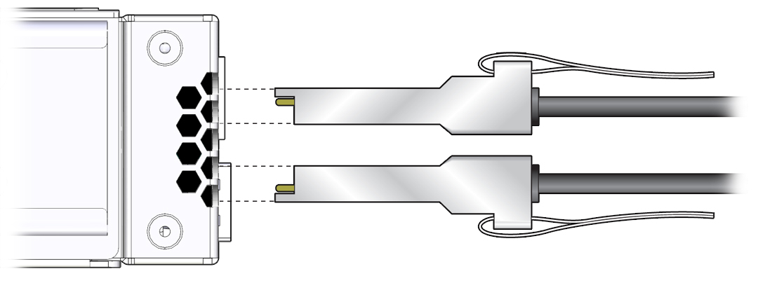

    Illustration shows the alignment of the InfiniBand cables.
    • If the connector stops or binds after about 1/4 in. (5 mm) travel, back out and repeat from Step 6.

    • If the connector stops or binds with about 1/8 in. (2 mm) still to go, back out and repeat Step 7.

  8. Continue to push the connector in until you feel a detent.
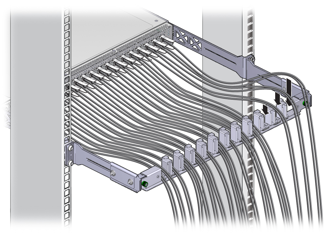
  9. Place the cable into the open slot on the cable management bracket.
    Illustration shows the InfiniBand cables being laid into the cable management bracket.
  10. Repeat Step 4 through Step 9 for all cables to be installed.
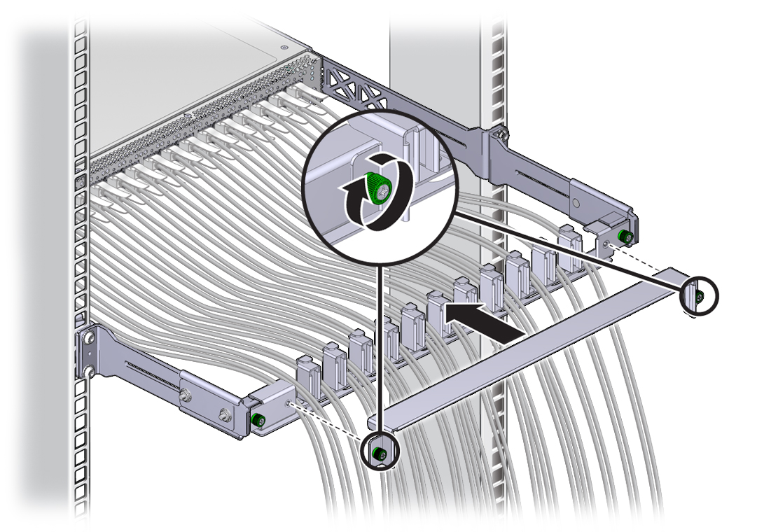
  11. Replace the cover for the cable management bracket and tighten the thumbscrews.
    Illustration shows the cover being put on the cable management bracket.
  12. Route the InfiniBand cables so that they do not interfere with other cables, or with servicing the switch or other systems.

    Use hook and loop fastener straps to bundle and secure the cables.


    Note - Do not use cable zip ties to bundle or secure the cable, because the ties damage the fibers inside the cable.


  13. Check that the Link LEDs for cabled links are lit green.

    If the Link LED is unlit, the link is down. If the Link LED flashes, there are symbol errors. See Check Link Status LEDs.

  14. If possible, close the rack doors to maintain EMI compliance.
  15. Check the link status.

    See Check Link Status.

Related Information