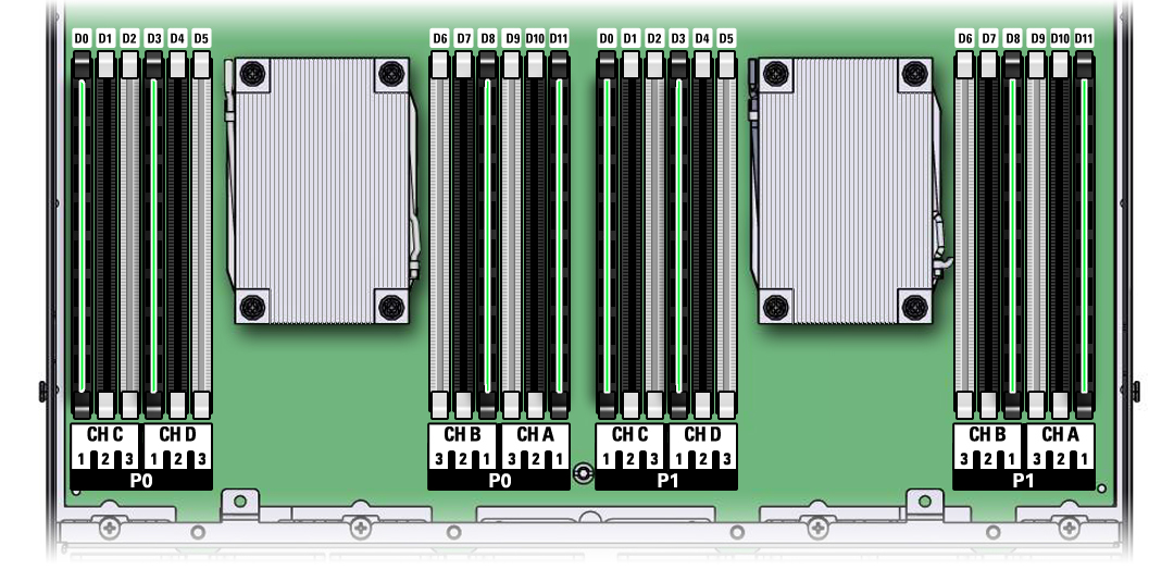
DIMM and Processor Physical Layout
The physical layout of the DIMMs and processor(s) is shown in the following figure. When viewing the storage server from the front, processor 0 (P0) is on the left. Notice that each processor, P0 and P1, have four memory channels that are labeled, from left to right, Ch C, Ch D, Ch B, and Ch A. Within each memory channel, only black sockets are populated with DIMMs.
Figure 3 DIMM and Processor Physical Layout
