Install a Processor
 | Caution - The green color-coded processor removal and replacement tool (part number G29477-002 or later) must be used to install the 8-core processor; otherwise, the processor or the processor socket might be damaged. |
 | Caution - Be careful not to touch the processor socket pins. The processor socket pins are very fragile. A light touch can bend the processor socket pins beyond repair. Always use the processor removal and replacement tool to remove and replace the processor. |
- Attach an antistatic wrist strap to your wrist, and then to a metal area on the chassis.
- Unpack the replacement processor, and place it on an antistatic mat.
-
Ensure that the replacement processor is identical to the failed processor that
was removed.
For a description of the processors that are supported by the server, refer to Storage Server Components in Oracle Exadata Storage Server X5-2 Extreme Flash Installation Guide.
-
Ensure that the two processor ILM assembly levers and the ILM assembly load
plate are in the fully open position.
For instructions for opening the processor ILM assembly levers and the load plate, see Step 6 through Step 8 of Remove a Processor.
-
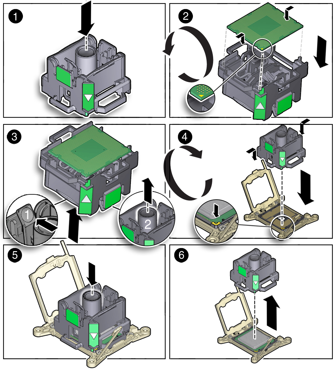
To install the replacement processor into the processor removal/replacement
tool, acquire the tool and perform the following steps.
- Press the button in the center of the tool to the down position [1].
- Turn the tool upside down, grasp the processor by its front and back edges and position the processor (circuit side up) in the tool so that the triangle on the corner of the processor aligns with the triangle on the side of the processor removal and replacement tool [2].
-
Lower the processor into the tool and press the tool release lever to
release the center button and engage the processor [3].
An audible click indicates that the processor is locked into place.
-
Properly position the tool over the processor socket and lower it into
place [4].
To properly position the tool in the processor socket, rotate the tool until the green triangle on the side of the tool is facing the front of the storage server and it is over the left side of the processor socket (when viewing the storage server from the front) and lower the tool into the processor socket.
- Press the center button on the tool down to release the processor so that it is installed in the socket [5].
-
Remove the processor removal and replacement tool [6].

-
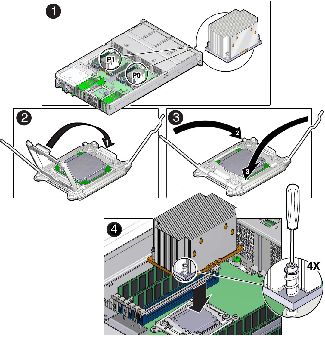
Visually check the alignment of the processor in the socket [1].
When properly aligned, the processor sits flat in the processor socket.

Caution - Do not press down on the processor. Irreparable damage to the processor or motherboard might occur from excessive downward pressure. Do not forcibly seat the processor into the socket. Excessive downward pressure might damage the socket pins.
-
Swing the processor ILM assembly load plate into the closed position
[2].
Ensure that the load plate sits flat around the periphery of the processor.

- Engage the socket release lever on the left side of the socket (viewing the storage server from the front) by rotating it downward and slipping it under the catch [3].
- Engage the socket release lever on the right side of the socket (viewing the storage server from the front) by rotating it downward and slipping it under the catch [3].
-
Use the syringe (supplied with the new or replacement processor) to apply
approximately 0.1 mL of thermal grease to the center of the top of the
processor.
To measure 0.1 ml of thermal grease, use the graduated scale on the thermal grease syringe.
Note - Do not distribute the grease; the pressure of the heatsink will do it for you when you install the heatsink. -
Inspect the heatsink for dust and lint.
Clean the heatsink if necessary.
-
Orient the heatsink so that the screws line up with the mounting posts
[4].
Note - The processor heatsink is not symmetrical. -
Carefully position the heatsink on the processor, aligning it with the mounting
posts to reduce movement after it makes initial contact with the layer of thermal
grease [4].

Caution - Avoid moving the heatsink after it has contacted the top of the processor. Too much movement could disturb the layer of thermal grease, causing voids, and leading to ineffective heat dissipation and component damage.
- Use a No. 2 Phillips screwdriver to tighten the screws alternately one-half turns until fully seated [4].
-
Return the storage server to operation.
- Lower the air baffle to the installed position.
- Install the storage server top cover.
- Return the storage server to the normal rack position.
-
Reconnect the power cords to the power supplies, and power on the storage
server.
See Reconnect Power and Data Cables and Power On the Storage Server. Verify that the power supply AC OK LED is lit.
-
Use Oracle ILOM to clear storage server processor faults.
Refer to the Oracle Integrated Lights Out Manager (ILOM) 3.2 Documentation Library at http://www.oracle.com/goto/ilom/docs for more information about the following steps.
-
To show storage server faults, log in to the storage server as
root using the Oracle ILOM CLI, and type the following
command to list all known faults on the storage server:
-> show /SP/faultmgmt
The storage server lists all known faults, for example:
-> show /SP/faultmgmt
  Targets:
      shell
      0 (/SYS/MB/P0)
  Properties:
  Commands:
      cd
      show
Alternatively, to list all known faults in the server, log into the Oracle Solaris OS and issue the fmadm faulty command, or log into the Oracle ILOM service processor from the Oracle ILOM Fault Management Shell and issue the fmadm faulty command. For more information about how to use the Oracle ILOM Fault Management Shell and supported commands, see the Oracle ILOM User's Guide for System Monitoring and Diagnostics Firmware Release 3.2.x in the Oracle Integrated Lights Out Manager (ILOM) 3.2 Documentation Library at http://www.oracle.com/goto/ilom/docs.
.
-
To clear the fault identified in Step 16a, type the following
command:
-> set /SYS/MB/P0 clear_fault_action=true
For example:
-> set /SYS/MB/P0 clear_fault_action=true
Are you sure you want to clear /SYS/MB/P0 (y/n)? y
Set ‘clear_fault_action’ to ‘true’
Alternatively, to clear all known faults in the server, log into the Oracle Solaris OS and issue the fmadm repair command, or log into the Oracle ILOM service processor from the Oracle ILOM Fault Management Shell and issue the fmadm repair command. For more information about how to use the Oracle ILOM Fault Management Shell and supported commands, see the Oracle ILOM User's Guide for System Monitoring and Diagnostics Firmware Release 3.2.x in the Oracle Integrated Lights Out Manager (ILOM) 3.2 Documentation Library at http://www.oracle.com/goto/ilom/docs.
-
To show storage server faults, log in to the storage server as
root using the Oracle ILOM CLI, and type the following
command to list all known faults on the storage server: