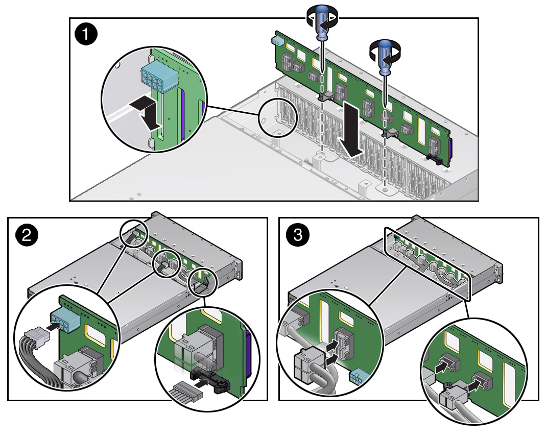
Install the Storage Drive Backplane
-
Lower the storage drive backplane into the storage server, and position it to
engage the standoff hooks [1].

-
Using a No. 2 Phillips screwdriver, install and tighten the two spring-mounted
screws to secure the storage drive backplane to the chassis [1].
Note - Due to its location, the left spring-mounted screw might be difficult to install with a standard No. 2 Phillips screwdriver. If you experience difficulty installing the screw, use a long No. 2 Phillips screwdriver or a torque driver with a long extension. -
Reconnect the cables to the storage drive backplane.
-
Reconnect the two power cables and the auxiliary signal cable to the
storage drive backplane [2].
Use the following cable part number table to ensure proper cable connections.
Cable Part NumberDescription7079291Auxiliary signal cable7064125Power cable, right7086654Power cable, center -
Reconnect the twelve NVMe cables to the storage drive backplane
[3].
To ensure proper NVMe cable connections, see Install NVMe Cables.
Note - After replacing the storage drive backplane, the NVMe cable connection test procedure must be performed before booting the storage server operating system. This procedure ensures that NVMe PCIe cabling is correct prior to booting the operating system. See Verify NVMe Cable Connections.
-
Reconnect the two power cables and the auxiliary signal cable to the
storage drive backplane [2].
-
Return the storage server to operation.
- Install the fan assembly door top cover.
-
Install the fan modules and close the fan assembly door.
See Install a Fan Module.
- Install all storage drives into the storage drive cage.
- Return the storage server to the normal rack position.
-
Reconnect the power cords to the power supplies, and power on the storage
server.
See Reconnect Power and Data Cables and Power On the Storage Server. Verify that the power supply AC OK LED is lit.
Note - IMPORTANT: When the disk backplane is replaced, the key identity properties (KIP) of the disk backplane is programmed by Oracle ILOM to contain the same KIP as the other quorum member components. If you have removed other quorum member components, you might need to manually program the product serial number (PSN) into the new disk backplane. For more information, refer to FRU Key Identity Properties (KIP) Automated Update.