| Exit Print View | |
Sun Netra CP3270 ATCA Blade Server User’s Guide |

|
Documentation, Support, and Training
Evaluating Product Compatibility
Preparing to Install the Blade Server
Installing Components and Blade Server
Installing Optional Components
Install an Advanced Mezzanine Card
Install an Advanced Rear Transition Module
Software and Firmware Upgrades
Software and Firmware Upgrades
Administering Parameters and Configurations
Administering User Accounts and Security
The following procedure provides a general guide for installing DIMMs as onboard memory. However, for specific directions on installing DIMMs, refer to the documentation that shipped with the DIMMs.
The blade server accommodates DDR3 (registered, ECC) @ 1066MHz DIMMs. For more information,
see ![]() Memory.
Memory.
Take antistatic precautions.
 | Caution - Always wear a grounded antistatic wrist strap when handling DIMMs. |
Access the blade server by performing one of the following procedures:
If the blade sever is new and not installed, unpack the blade server.
If the blade server is installed in an ATCA shelf, remove the blade server from the shelf.
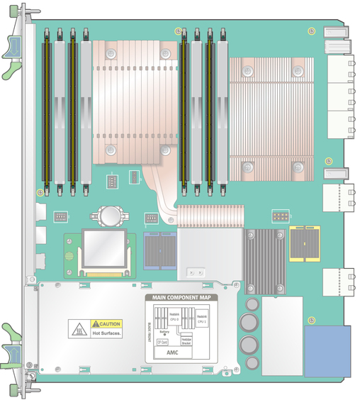
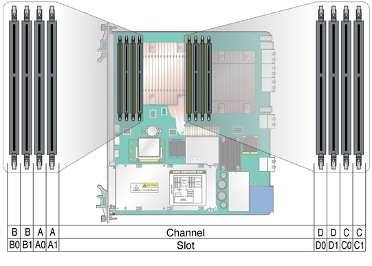
Locate the DIMM channels and connectors on the blade server, as shown in the following figure.

Select the channels and slots where you will install the DIMM.

Four channels are available: A, B, C, and D. Each channel has two DIMM slots. For example, channel A has slots A0 and A1, channel B has slots B0 and B1, and so on.
Populate DIMMs in allocations of four or eight:
If using four DIMMs, install all of them in slots 0 (A0, B0, C0 and D0). Filler panels must be installed in slots A1, B1, C1, and D1.
If using eight DIMMs, fill all eight slots.
Remove the DIMM from its protective packaging, holding the module only by the edges.
Note - Before installing a replacement DIMM, verify that the new DIMM is the same capacity as its paired DIMM.
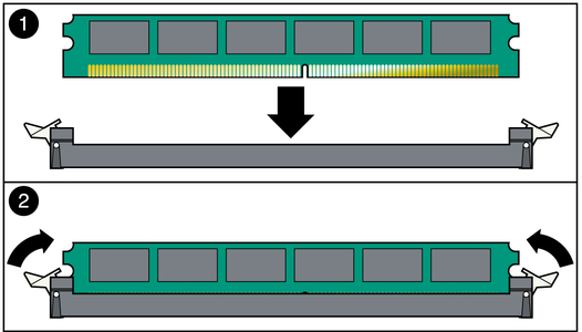
Holding the DIMM upright to the blade server, insert the bottom edge of the DIMM into the bottom of the slot’s hinge-style connector, as shown in the following figure.
 | Caution - Evenly engage the DIMM in its hinge-style slot. Uneven contact can cause shorts that will damage the blade server. Do not rock the DIMM into place. Ensure that all contacts engage at the same time. You will feel or hear a click when the DIMM properly seats in the connector. |
The socket and module are both keyed, which means that the DIMM can be installed only one way. With even pressure, push simultaneously on both upper corners of the DIMM until its bottom edge (the edge with the gold fingers) is firmly seated in the connector.

Press the top edge of the DIMM toward the blade server until the retainer clips click into place in the notches on the DIMM sides.
The small metal retainer clips on each side of the DIMM slot are spring-loaded and should click into place in the notches on the sides of the DIMM.