
To begin creating a CVSG-VE Location in App Net Manager:
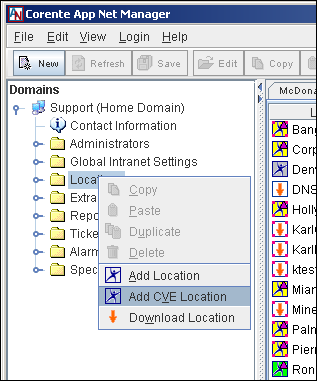
Select the File menu and choose Add CVE Location; or
Right-click the Locations category in the domain directory and choose Add CVE Location.
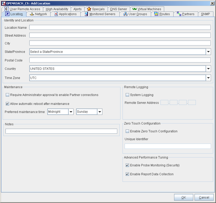
The Location form will be displayed for the CVSG-VE Location. CVSG-VE Location forms capture settings similar to the settings available on the ordinary Location form, but due to differences in functionality, some options and tabs are not available.
On the first tab of the form, the Location tab, fill in the name, physical location, time zone, maintenance, Zero Touch Installation, and advanced performance tuning preferences for the CVSG-VE Location.
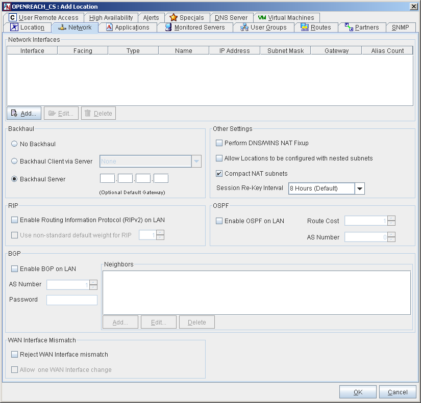
On the Network tab of the Location form, you must define a LAN/WAN Interface (for a CVSG-VE Location in the Peer configuration) or a LAN and a WAN interface (for a CVSG-VE Location in the Inline configuration).
To define the interface(s), select the Add button in the Network Interfaces section.
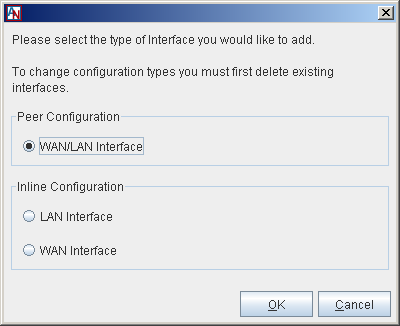
On the window that is displayed, select the interface you would like to define and click OK.
A. Peer Configuration
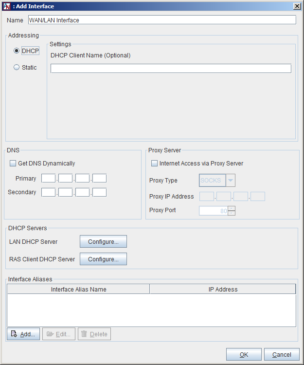
A Peer CVSG-VE Location uses a single Ethernet interface and can reside in any location on the LAN. To define a Peer CVSG-VE Location, select WAN/LAN Interface and click OK.
On the window that is displayed, select the method by which the CVSG-VE Location will be assigned addressing information for this interface (either a Static address assignment or a dynamic assignment via DHCP). A typical configuration would use DHCP.
Use the DNS section to identify the DNS servers that will be used by this CVSG-VE Location to resolve DNS names. If you are using DHCP to assign addressing information to one or more interfaces of the CVSG-VE Location, you can select Get DNS Dynamically to obtain the addresses of the servers dynamically. Complete the Proxy Server section if this CVSG-VE must connect to the Internet via a proxy server.
Use the options in the DHCP Servers section to configure the CVSG-VE Location as a DHCP server for VMs and computers on its LAN or for its Corente Client partners. For more information, refer to the “LAN DHCP Server” and “RAS Client DHCP Server” sections in the II B. Corente Services Policy Definition and Provisioning manual.
Use the Interface Aliases section to define alias address(es) for this interface to use when configuring port forwarding for VMs or servers on the LAN. For more information, refer to the “Port Forwarding” section of “Appendix B: Additional Tube Configurations” in the II B. Corente Services Policy Definition and Provisioning manual.
B. Inline Configuration
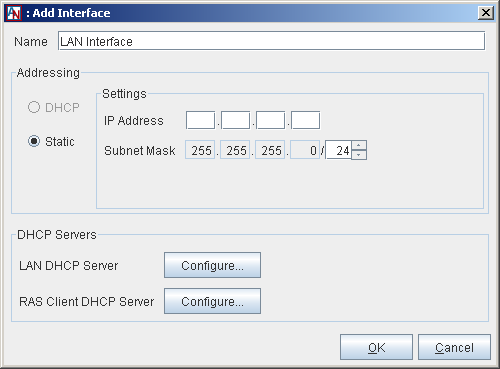
An Inline CVSG-VE Location uses two Ethernet interfaces (one that connects to your LAN, and one that connects to an external network, e.g. the Internet) and acts as the gateway device for a LAN. To define an Inline CVSG-VE Location, begin by selecting LAN Interface and clicking OK.
On the window that is displayed, enter the addressing information for the LAN interface. The LAN address of an Inline CVSG-VE Location must always be static. You must manually enter an IP address and subnet mask for this interface.
Use the options in the DHCP Servers section to configure the CVSG-VE Location as a DHCP server for VMs or computers on its LAN or for its Corente Client partners. For more information, refer to the “LAN DHCP Server” and “RAS Client DHCP Server” sections in the II B. Corente Services Policy Definition and Provisioning manual.
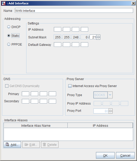
After defining the LAN interface for the Inline CVSG-VE Location, you must also define the WAN Interface.
Select the method by which the CVSG-VE Location will be assigned addressing information for the WAN interface (either a Static address assignment, a dynamic assignment via DHCP, or by using PPPOE). A typical configuration would use DHCP.
Use the DNS section to identify the DNS servers that will be used by this CVSG-VE Location to resolve DNS names. If you are using DHCP to assign addressing information to one or more interfaces of the CVSG-VE Location, you can select Get DNS Dynamically to obtain the addresses of the servers dynamically. Complete the Proxy Server section if this CVSG-VE must connect to the Internet via a proxy server.
Use the Interface Aliases section to define alias address(es) for this interface to use when configuring port forwarding for VMs or servers on the LAN. For more information, refer to the “Port Forwarding” section of “Appendix B: Additional Tube Configurations” in the II B. Corente Services Policy Definition and Provisioning manual.
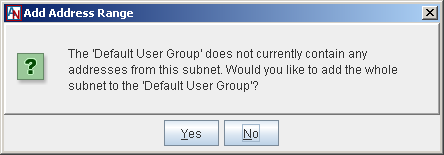
When you define a static address for the WAN/LAN interface or LAN interface of your CVSG-VE Location on the Network tab, a dialog box will appear that asks if you would like to add the entire subnet of that IP address to the Default User Group for your CVSG-VE Location. The Default User Group contains all of the local addresses that will be participating in the secure network, including both addresses on the CVSG-VE Location’s LAN and the addresses of the CVSG-VE Location’s VMs.
When you click Yes, the entire subnet will be added to the Default User Group. You can access the User Group tab in the CVSG-VE Location form later to add additional addresses to the Default User Group or exclude certain addresses, if you would like.
When you click No, the Default User Group will remain undefined. You must manually add addresses to the Default User Group on the User Group tab. Remember that if you want to share the application(s) on any VM in the CVSG-VE Location with other Locations in your secure network, you must add the IP address(es) of the VM(s) to the Default User Group.
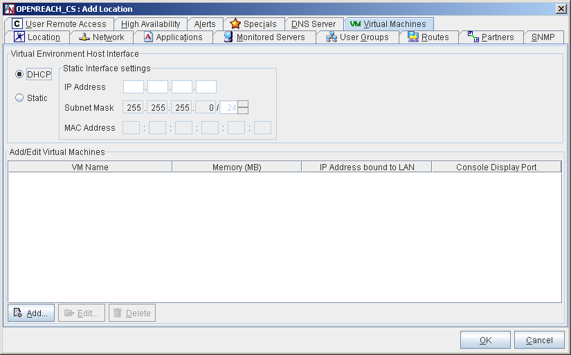
After completing the basic Location and Network configuration for the CVSG-VE Location, access the Virtual Machines tab.
In the Virtual Environment Host section, choose how an IP address will be assigned to the virtual host in the CVSG-VE Location. If the address will be assigned dynamically by a DHCP server, choose DHCP. If you would like to assign a specific address to the virtual host, choose Static and enter an IP address in the adjacent field. For both options, remember that any address assigned to the virtual host must be on the same subnet as the LAN interface (or WAN/LAN interface) of the CVSG-VE Location.
When DHCP is enabled, the MAC address of the interface will be displayed in the MAC Address field.
Any existing VMs that are currently installed on the CVSG-VE Location will be listed on this tab. Click the Add button to add a new VM. In this example, we are adding a VM named
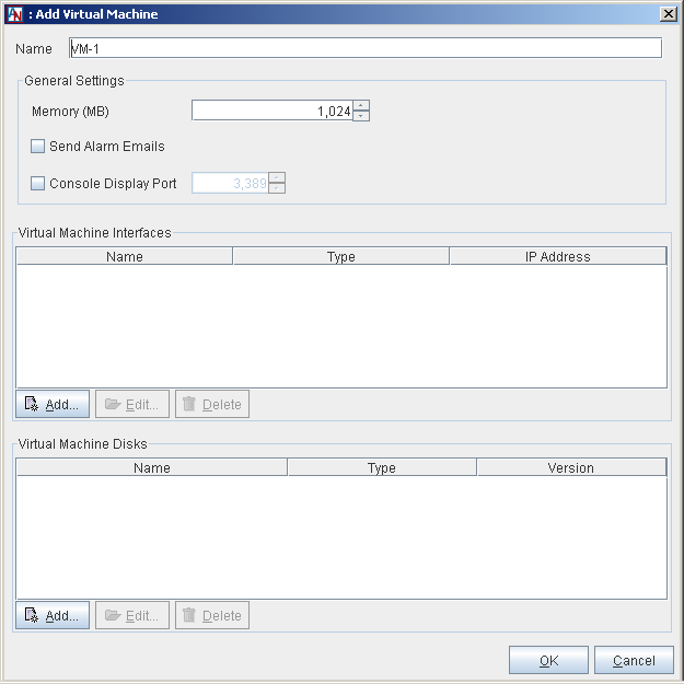
VM_1.Fill out the Add Virtual Machine window as follows:
Name: Enter a name for the VM in this field. This name will function like a host name for the VM.
General Settings:
Memory (MB): This sets the amount of RAM that is allocated and given to the VM when it is running. The amount of memory specified in this field will be requested from the CVSG-VE Location, so it must be available or made available as free memory when attempting to start the VM and will not be available to the CVSG-VE Location while the VM is running. Remember that the amount of memory that is available for your all of the VMs on this CVSG-VE Location is limited by the amount of memory on the CVSG-VE Location hardware itself. The default is 1 GB (1024 MB), but you may modify this parameter if necessary. The maximum amount of memory that can be assigned to a VM is 3584 MB.
Send Alarm Emails: If you would like to be alerted via email when alarms are generated concerning this VM, select this checkbox. Notifications will be sent to the email addresses specified on this CVSG-VE's Location Alerts tab and/or the default email addresses specified for this domain on the Alerts tab of the Domain Preferences window. If you do not select this checkbox, no emails will be sent; however, the alarms will be displayed on the Alarms and Events interface of App Net Manager.
Console Display Port: Select this option to enable access to the VM via a the RDP application. In the adjacent field, enter the port number on the CVE Location that will be used by the application to contact the VM. The default port for the first VM is 3389. Each subsequent VM will increment this default port by one, so that each VM is contacted via a different port. To connect to a VM via RDP, use the IP address of this CVE Location's Virtual Environment Host Interface and the Console Display Port number for that specific VM.
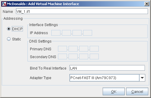
Virtual Machine Interfaces: Click Add to add a new interface to this VM. On the screen that is displayed, select the method with which this VM will be assigned its IP addressing information:
DHCP: If you would like this VM to receive its IP address via DHCP from the CVSG-VE or a DHCP server on your LAN, select DHCP. The VM will receive an address on the same subnet as the LAN address (if Inline) or WAN/LAN address (if Peer) of the CVSG-VE.
DNS Settings: Select DNS from DHCP if the IP addresses of the DNS server(s) will be provided by the DHCP server when it serves the VM's IP address.
Adapter Type: Select a specific network adapter to be used by the interface. This is needed specifically for VMs made in Virtual Box that use the Windows 7 or Windows Vista operating systems so that the network will come up properly. You can choose from the PCnet-PCI II (Am79C970A), PCnet-FAST III (Am79C973), Intel PRO-1000 MT Desktop (82540EM), Intel PRO/1000 T Server (82543GC), or Intel PRO/1000 MT Server (82545EM) interfaces.
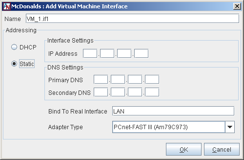
Static: If you would like to assign a static address to this VM, select Static.
IP Address: Enter the IP address that you would like assigned to this VM. This address must be on the same subnet as the LAN address (if Inline) or WAN/LAN address (if Peer) of the CVSG-VE.
DNS Settings: Enter the IP address(es) of the primary (and secondary, if applicable) DNS servers that will be used by this VM to resolve DNS names.
Adapter Type: Select a specific network adapter to be used by the interface. This is needed specifically for VMs made in Virtual Box that use the Windows 7 or Windows Vista operating systems so that the network will come up properly. You can choose from the PCnet-PCI II (Am79C970A), PCnet-FAST III (Am79C973), Intel PRO-1000 MT Desktop (82540EM), Intel PRO/1000 T Server (82543GC), or Intel PRO/1000 MT Server (82545EM) interfaces.
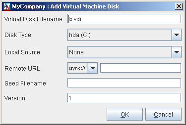
Virtual Machine Disks: Select Add to add a new disk to the VM. One of each of the following types of disks can be added to a VM: hda, hdb, hdc (for VMs using Linux or Solaris), C, D, E (for VMs using Windows), floppy, and dvd.
Click OK when you are finished to store this VM on the CVSG-VE.
If you are installing any disk images for a VM remotely via a remote distribution server, you must make sure that the CVSG-VE Location will have access to the appropriate server(s) supplying the disk images. This might mean that you need to access the Partners tab and partner the CVSG-VE Location with the Corente Virtual Services Gateway on the distribution server’s LAN. For more information about partnering a CVSG-VE Location, refer to Section 6.3.7, “Partners Tab”.
Click OK on the Location form to store the new CVSG-VE Location’s basic configuration. Save your changes to App Net Manager by clicking the Save button on the toolbar.
If installing a disk image via a remote distribution server that is behind another Corente Virtual Services Gateway, access the Partners tab of that gateway’s Location form and partner it with the CVSG-VE Location, granting the appropriate permissions that will allow the CVSG-VE Location to download files from the server. Complete this configuration for as many distribution servers behind as many gateways or CVSG-VE Locations as the CVSG-VE Location will need to access.
If you do not have Zero Touch Installation enabled for this CVSG-VE, download the CVSG-VE Location configuration to a USB flash drive. All other configuration file installation options that are used by ordinary Corente Virtual Services Gateways will be unavailable; you must install the configuration file on a CVSG-VE Location using a USB flash drive. For more information on downloading a Location configuration to a USB flash drive, refer to the “Download the Configuration File to a Floppy Disk or USB Flash Drive” section of the II A. Corente Virtual Services Gateway Hardware Preparation and Deployment manual. For more information about Zero Touch Installation, refer to the “Enable Zero Touch Installation” section of the II B. Corente Services Policy Definition and Provisioning manual.
Create a vmhost installation DVD or USB flash drive.
The image file for the installation DVD can be downloaded from the following location: http://www.corente.com/pub/release/current/iso/ and then burned to a DVD. The file name is
or-vmhost, followed by the current version number. Make sure to physically label the DVD that you create, as booting any machine with this DVD in the DVD drive will reformat the machine’s hard drive.Prepare a portable USB flash drive that uses the FAT format and has 2 GB of free space. The
.zipfile for the executable to create an installation USB flash drive can be downloaded from the following location: http://www.corente.com/pub/release/current/tsg/VmUsbKeydriveInstall.zip. When the.zipfile has downloaded, extract it into a new directory. When it has finished extracting, there will be an.exefile inside the new directory. Double-click this.exefile to open the USB flash drive installer. Click Next to move through the screens and create the bootable USB flash drive. When prompted, insert your flash drive into a USB port on your computer. The installer will automatically detect the removable drive on which to install the bootable USB flash drive files.CautionMake sure this is the correct drive. You could damage your system if the installer loads the files onto your hard drive. Make sure to physically label the USB flash drive that you create, as booting any machine with this drive in the USB port will reformat the machine’s hard drive.
Attach a monitor/keyboard to the host machine and boot it from the vmhost installation DVD or USB flash drive. This will format the hard disk and install the CVSG-VE Location software. There will be no warnings or confirmations that this is taking place, so, again, make sure this DVD/USB flash drive is never loaded in machine that you do not want to turn into a CVSG-VE Location.
If requested, insert the USB memory device containing the CVSG-VE Location configuration into the USB drive of the new CVSG-VE Location. The initial configuration of the CVSG-VE Location takes about 30 minutes. After this time period, if the CVSG-VE Location is connected to the Internet, the CVSG-VE Location will activate with the SCP and appear as Active in App Net Manager.
If the VM was configured to use either USB or CD/DVD media for any of the disk image file fetches of a VM, it will be requested by a message emitted to the CVSG-VE Location console. Follow the on-screen instructions to install the disk image.
If the VM was configured to fetch any of the disk image files from a remote server, it will attempt to download the disk image(s) via the path you specified on the Virtual Machines tab. Follow the on-screen instructions to install the disk image.
Fetch Behavior
Depending on how you fill out the fetchlocal,
fetchremote, and fetchseed
parameters when a installing a VM’s disk image onto the CVSG-VE
Location, the CVSG-VE Location will install the disk image in the
following manner:
Table 6.1 Fetch Behavior
| FetchRemote | FetchLocal | FetchSeed | Result |
|---|---|---|---|
| Invalid configuration | |||
| seed.vdi | If no app.vdi file, copy from seed | ||
| usb, cd or dvd | If version mismatch, or no local app.vdi file, copy from media | ||
| usb, cd, or dvd | seed.vdi | Copy from media to app.vdi and also create seed | |
| rsync://sss, http://sss, https://sss or ftp://sss | If version mismatch, or no app.vdi file, fetch remotely | ||
| rsync://sss, http://sss, https://sss or ftp://sss | seed.vdi | If no app.vdi file, copy seed as initial state, then do rsync, http, https or ftp to update | |
| rsync://sss, http://sss, https://sss or ftp://sss | usb, cd or dvd | If no app.vdi file, copy from media as initial state, then do rsync, http, https or ftp to update | |
| rsync://sss, http://sss, https://sss or ftp://sss | usb, cd or dvd | seed.vdi | Copy file to seed. If no app.vdi file, copy seed, then do rsync. If version mismatch, fetch remotely |