Understanding PCIe Root Complex Connections
All 16 PCIe slots support PCIe cards with the following characteristics:
-
Hot-plug low-profile adapters
-
x8 Gen1, x8 Gen2, and x8 Gen3 cards
In addition, the following PCIe slots support x16 Gen3 cards at full bandwidth:
-
Slot 3
-
Slot 4
-
Slot 7
-
Slot 8
-
Slot 11
-
Slot 12
-
Slot 15
-
Slot 16
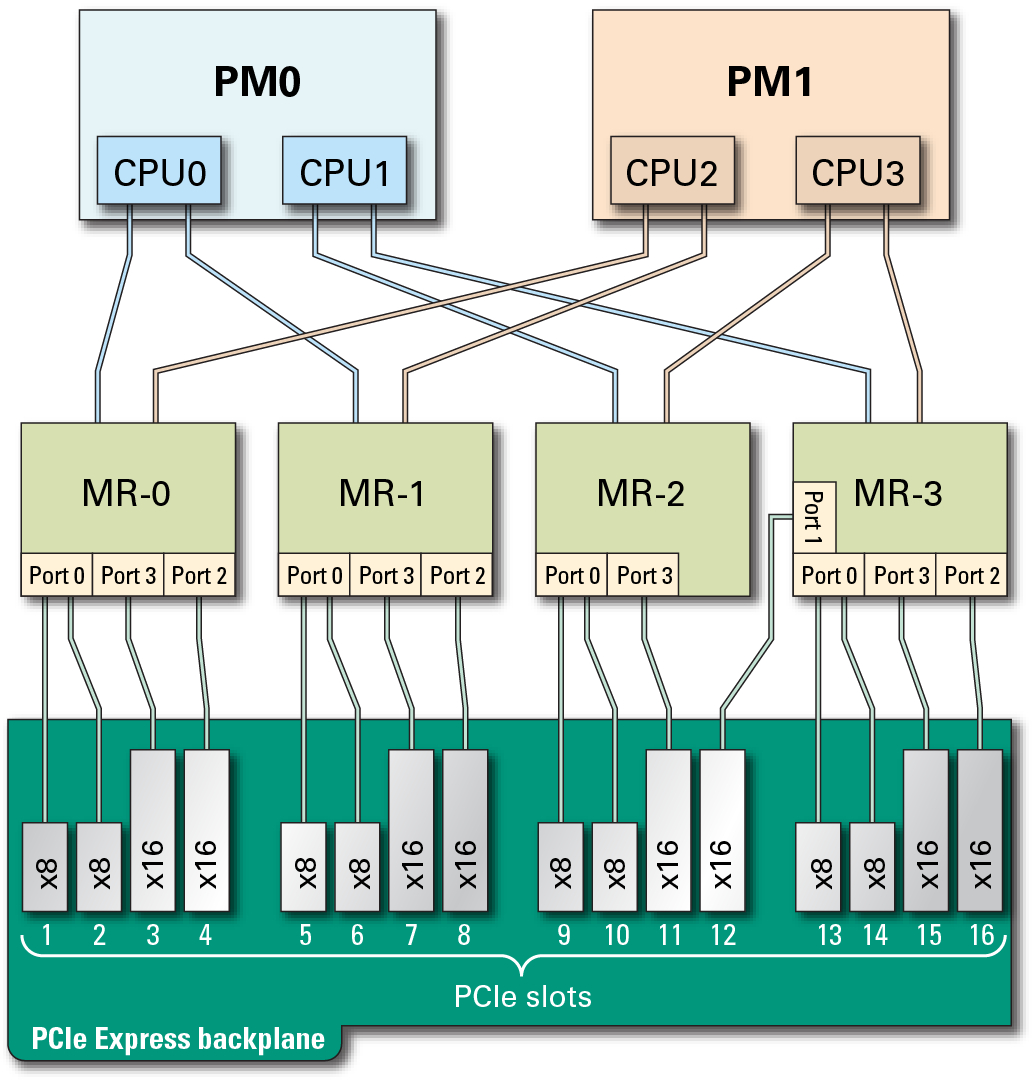
A root complex is the CMP circuitry that provides the base to a PCIe I/O fabric. Each PCIe I/O fabric consists of the PCIe switches, PCIe slots, and leaf devices associated with the root complex. Understanding the relationship of the PCIe root complexes to the PCIe I/O fabrics will help you properly assign devices when configuring Oracle VM Server for SPARC logical domains.

This diagram illustrates the root complex connections between the four CPUs and the 16 PCIe I/O slots. Each CPU supports all I/O root complex fabrics. In single-PM configurations, all PCIe slots are available. In addition, all 16 PCIe slots are still available even if PM1 goes offline.
The port ID values shown in the diagram correspond to the pci@ values reported in the showdevs command output.
|
If you are reviewing root complex changes after adding a second processor module, return to Server Upgrade Process.