| Exit Print View | |
Sun Datacenter InfiniBand Switch 648 Topic Set |

|
Documentation, Support, and Training
Understanding ILOM on the Switch
Administering ILOM (Web Interface)
Understanding Service Procedures
Inspect the Power Supply Hardware
Inspect the Power Supply Connectors
Servicing the Fabric Cards and Fabric Card Fillers
Inspect the Fabric Card Chassis
Inspect the Fabric Card Retainer Bolts
Inspect the Fabric Card XBOW Connectors
Remove a Fabric Card or Fabric Card Filler
Install a Fabric Card or Fabric Card Filler
Servicing the InfiniBand Cables
Inspecting the InfiniBand Cables
Inspect the InfiniBand Cable Hardware
Inspect the InfiniBand Cable Connectors
Inspect the Line Card Retainer Bolts
Inspect the Line Card XBOW Connectors
Inspect the Line Card CXP Connectors
Doing Supportive Software Tasks
 | Caution - Installing the line card is a methodical task and cannot be rushed. To prevent damage to the line card or the midplane XBOW connectors, pay close attention to the procedure and work slowly. |
Identify the prerequisite and subsequent tasks you must perform in conjunction with this procedure, to achieve a goal.
See the table in ![]() Servicing the Line Cards.
Servicing the Line Cards.
If a line card filler occupies the slot where a line card is to be installed, follow these steps.
Otherwise, continue to ![]() Step 3.
Step 3.
Inspect the replacement line card.
Inspect the slot where the line card will install for debris and loose gasketing.
 | Caution - You must remove any debris or gasketing material from the line card slot prior to installing the line card. Failure to clean the slot might result in damage to the line card or midplane XBOW connectors upon installation of the line card. |
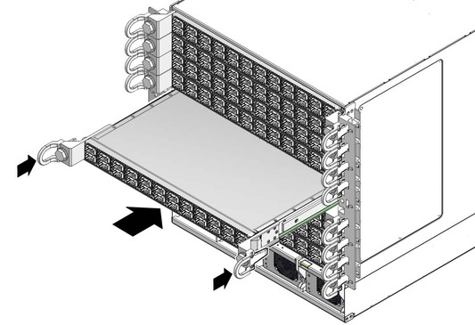
Lift the line card from the work surface and orient it horizontally, with the link LEDs across the bottom.
Insert the line card into the chassis at the vacant slot.
Ensure that the line card is square to the chassis and not skewed.

Note - Once the line card is about halfway into the slot, it is no longer necessary to bear the weight of the line card.
Continue to slide the line card in, maintaining a squared orientation.
When you feel resistance, stop.
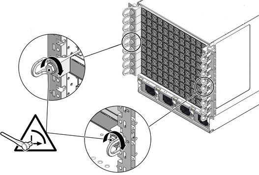
While pressing the line card in with one hand, rotate the retainer bolts clockwise by hand so that they engage.
When you feel resistance in the retainer bolts, stop.
Using a 20 mm socket and ratchet, turn the left retainer bolt 1/4 turn clockwise.

Turn the right retainer bolt 1/4 turn clockwise.
 | Caution - Do not turn the retainer bolts more than 1/4 revolution each time. Turning more than 1/4 turn damages the line card and midplane XBOW connectors. |
Repeat ![]() Step 9 and
Step 9 and ![]() Step 10 about 12 times until you feel resistance to turning
and the line card is flush to the front of the chassis.
Step 10 about 12 times until you feel resistance to turning
and the line card is flush to the front of the chassis.
Give each retainer bolt a torque of 2.0 ft-lb (0.27 kg-m).
Turn the left retainer bolt 1/4 turn counter-clockwise.
Turn the right retainer bolt 1/4 turn counter-clockwise.
Repeat ![]() Step 13 and
Step 13 and ![]() Step 14 twice to relieve board deflection.
Step 14 twice to relieve board deflection.
Verify that the line card is properly seated in the slot.
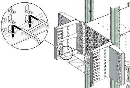
Lift the cable shelf into a horizontal orientation, with the long rolled edge towards you.
Locate where you want to install the cable shelf.
Move the cable shelf between and just above the branches of the cable tree for the slot where you want to install the shelf.
Continue to move the shelf in, then lower the shelf into the holes of the tabs.

Power on the line card.
See ![]() Power On a Line Card.
Power On a Line Card.