Use Case: Configuring an EVS Network Topology
Objective – This use case shows how to set up a network topology consisting of EVS components for a specific tenant.
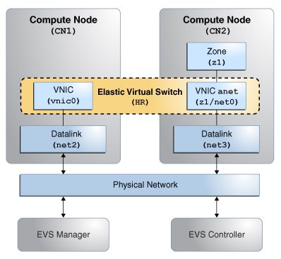
The network is shown in the following figure:
Figure 21 Elastic Virtual Switch Configuration for a Tenant

The network consists of the following components:
-
One EVS controller node
-
One EVS Manager node
-
Two compute nodes CN1 and CN2, each with its own datalink
-
A virtual machine z1 to be hosted by CN2
The following configurations, not shown in the figure, will be implemented:
-
The controller's hostname is evs-controller.example.com.
-
The controller is configured as a VLAN.
-
The elastic virtual switch (HR) is created for a tenant, tenantA.
-
The subnet for tenantA is called HR/hr_ipnet.
In this sample case, the necessary EVS packages are already properly installed on all nodes. Further, SSH authentication for evsuser has been completed on all nodes. The configuration is performed as evsuser on the EVS Manager node.
Configure the EVS Manager node to connect with the controller.
manager$ su - evsuser
evsuser@manager$ evsadm set-prop -p controller=ssh://evsuser@evs-controller.example.com
Connect to the controller. The configuration consists of setting up a VLAN with a range of VLAN IDs and creating uplink ports for the compute nodes. The resulting configuration is displayed.
evsuser@controller$ evsadm set-controlprop -p l2-type=vlan
evsuser@controller$ evsadm set-controlprop -p vlan-range=200-300
evsuser@controller$ evsadm set-controlprop -h CN1 -p uplink-port=net2
evsuser@controller$ evsadm set-controlprop -h CN2 -p uplink-port=net3

evsuser@controller$ evsadm show-controlprop -p l2-type,vlan-range,uplink-port
NAME             VALUE         DEFAULT        HOST
l2-type          vlan          vlan           --
vlan-range       200-300       --             --
uplink-port      net2          --             CN1
uplink-port      net3          --             CN2
Create the switch for the tenant and specify the tenant's subnet. The resulting configuration is displayed.
evsuser@controller$ evsadm create-eps -T tenantA HR
evsuser@controller$ evsadm add-ipnet -T tenantA -p subnet=192.0.2.0/27 HR/hr_ipnet

evsuser@controller$ evsadm
NAME         TENANT     STATUS   VNIC    IP             HOST
HR           tenantA    --       --      hr_ipnet       --
   vport0    --         free     --      192.0.2.2/27   --

evsuser@controller$ evsadm show-vportprop -p macaddr,ipaddr HR/vport0
NAME         TENANT     PROPERTY  PERM  VALUE            DEFAULT POSSIBLE
HR/vport0    tenantA    ipaddr    r-    192.0.2.2/27     --      --
HR/vport0    tenantA    macaddr   r-    2:8:20:d8:da:10  --      --

evsuser@controller$ evsadm show-evs -L
EVS   TENANT     VID   VNI
HR    tenantA    200   --
Connect to CN1 to configure it. The configuration consists of a VNIC to enable CN1 to connect to the switch. The IP address to assign is obtained by checking the allowed IP address for the VNIC.
evsuser@CN1$ evsadm set-prop -p controller=ssh://evsuser@evs-controller.example.com

evsuser@CN1$ dladm create-vnic -t -T tenantA -c HR vnic0
evsuser@CN1$ dladm show-linkprop -p allowed-ip vnic0
LINK     PROPERTY     VALUE      EFFECTIVE  DEFAULT   POSSIBLE
vnic0    allowed-ips  192.0.2.2  192.0.2.2  --        --

evsuser@CN1$ ipadm create-ip -t vnic0
evsuser@CN1$ ipadm create-addr -t -a 192.0.2.2 vnic0
Connect to CN2 to configure it. The configuration consists of creating the zone for the tenant. The zone is configured with a VNIC's anet resource to provide connectivity to the switch. Note that you still need to complete zone configuration by logging in after the zone has booted. The remaining configuration is not related to EVS and is not covered in this example.
evsuser@CN2$ evsadm set-prop -p controller=ssh://evsuser@evs-controller.example.com

evsuser@CN2$ zonecfg -z z1
zonecfg:z1> create
create: Using system default template 'SYSdefault'
zonecfg:z1> set zonepath=/export/zones/z1
zonecfg:z1> set tenant=tenantA
zonecfg:z1> select anet linkname=net0
zonecfg:z1:anet> set evs=HR
zonecfg:z1:anet> end
zonecfg:z1> commit
zonecfg:z1> exit
evsuser@CN2$

evsuser@CN2$ zoneadm -z z1 install
...
evsuser@CN2$ zoneadm -z z1 boot
...
evsuser@CN2$ zlogin -C z1
...

evsuser@CN2.z1$ dladm show-vnic -c
LINK          TENANT   EVS  VPORT   OVER  MACADDRESS       IDS
z1/net0       tenantA  HR   vport0  net3  2:8:20:d8:da:10  VID:200

evsuser@CN2.z1$ ipadm
NAME        CLASS/TYPE   STATE   UNDER   ADDR
lo0         loopback     ok      --      --
   lo0/v4   static       ok      --      127.0.0.1/8
   lo0/v6   static       ok      --      ::1/128
net0        ip           ok      --      --
   net0/v4  inherited    ok      --      192.0.2.3/27