Trunk Aggregations
Based on the IEEE 802.3ad standard, trunk aggregations work by enabling multiple flows of traffic to be spread across a set of aggregated ports. The clients configured over the aggregations acquire a consolidated bandwidth of the underlying links. Each network port is associated with every underlying datalink.
You might use this type in the following situations:
-
For systems in the network that run applications with distributed heavy traffic, you can dedicate a trunk aggregation to that application's traffic to take advantage of the increased bandwidth.
-
For sites with limited IP address space that require large amounts of bandwidth, you need only one IP address for the trunk aggregation of datalinks.
-
For sites that need to hide any internal datalinks, the IP address of the trunk aggregation hides these datalinks from external applications.
-
For applications that need reliable network connection, trunk aggregation protects network connections against link failure.
Unless you specify otherwise, an aggregation is automatically created as a trunk aggregation.
Using a Switch
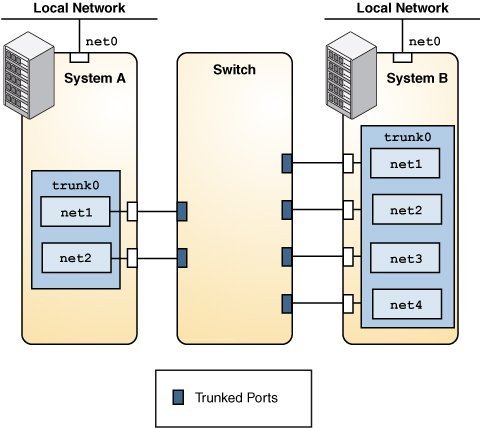
Systems with trunk aggregations might use an external switch to connect to other systems. See the following figure.
Figure 2 Trunk Aggregation Using a Switch

System A's aggregation consists of two datalinks, while System B's aggregation consists of four. All the links of both aggregations are connected to the aggregated ports on the switch.
If aggregations and switches are used together, the switch must support the IEEE 802.3ad standard and the switch ports must be configured for aggregation.
Back-to-Back Trunk Aggregation Configuration
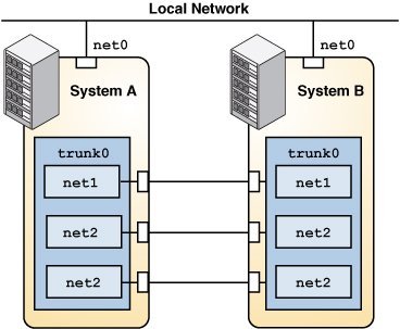
Trunk aggregations can be set up as a back-to-back configuration. Two systems are directly connected to run parallel aggregations, as shown in the following figure.
Figure 3 Back-to-Back Trunk Aggregation Configuration

The back-to-back setup enables both systems to provide redundancy, high availability, and high-speed communication between both systems.
Back-to-back aggregations are commonly used in mirrored database server setups in large deployments such as data centers. Both servers must be updated together and therefore require significant bandwidth, high-speed traffic flow, and reliability.
Using a Switch With the Link Aggregation Control Protocol
If the switch supports Link Aggregation Control Protocol (LACP), such as Oracle Switch ES1-24 (see Sun Ethernet Fabric Operating System in LA Administration Guide), you can enable LACP for both the switch and the system.
LACP is more reliable in detecting datalink failures. Without LACP, to detect failures, an aggregation relies only on the link state reported by the device driver. With LACP, LACP data units (LACPDUs) are exchanged at regular intervals to ensure that the aggregated datalinks can send and receive traffic. LACP also detects some misconfiguration cases, for example, when the grouping of datalinks does not match between the two peers.
-
off – Default mode for aggregations. The system does not generate LACPDUs.
-
active – System generates LACPDUs at specified intervals.
-
passive – System generates an LACPDU only when it receives an LACPDU from the switch. When both the aggregation and the switch are configured in passive mode, they do not exchange LACPDUs.
LACP can be set to one of three modes:
Defining Aggregation Policies for Load Balancing
To distribute load across the available aggregation links and establish load balancing, select from the following load specifiers:
-
L2 – Determines the outgoing link by using the MAC (L2) header of each packet
-
L3 – Determines the outgoing link by using the IP (L3) header of each packet
-
L4 – Determines the outgoing link by using the TCP, User Datagram Protocol (UDP), or other Upper Layer Protocol (ULP) (L4) header of each packet
Any combination of these policies is also valid. The default policy is L4.