Overview of Private VLANs
Private VLAN (PVLAN) technology defined in RFC 5517 enables you to divide a VLAN into sub-VLANs to isolate network traffic. A regular VLAN is a single broadcast domain. When you configure a PVLAN, the single broadcast domain is partitioned into smaller subdomains. The standard (IEEE 802.1Q) VLAN is called the primary VLAN and the sub-VLANs are called the secondary VLANs. The secondary VLANs can be either isolated VLANs or community VLANs.
-
The ports that are associated with an isolated VLAN can communicate only with the primary VLAN and not with any other secondary VLAN. You can create only one isolated VLAN within a primary VLAN domain.
-
The ports associated with community VLAN can communicate with the primary VLAN and the other ports that are in the same community VLAN. You can create multiple community VLANs within a primary VLAN domain.
In Oracle VM Server for SPARC that has a configured PVLAN, the inter-vnet-links feature supports the communication restrictions of isolated and community PVLANs. Inter-vnet-links are disabled for isolated PVLANs and are enabled only for virtual networks that are in the same community for community PVLANs. Direct traffic from other virtual networks outside of the community is not permitted. For more information, see Using Private VLANs in Oracle VM Server for SPARC 3.6 Administration Guide.
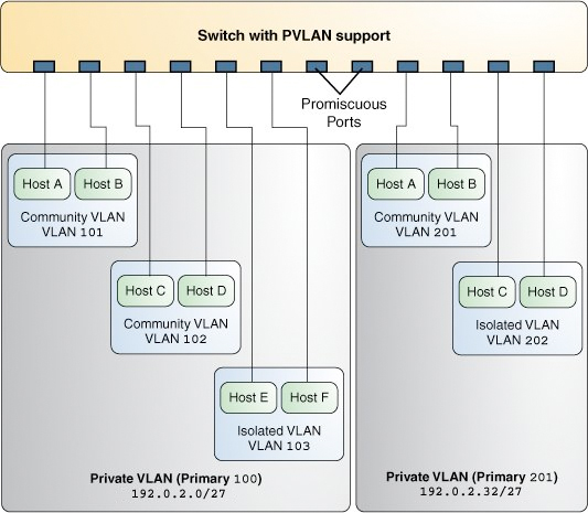
The following figure shows a simple PVLAN configuration with two PVLANs configured on a switch that supports PVLAN.
Figure 11 Private VLAN

In the figure, the private VLAN with the primary VLAN ID 100 has three secondary VLANs with secondary VLAN IDs 101, 102, and 103. Two of the secondary VLANs are community VLANs with the hosts Host A and Host B and Host C and Host D, and the other is an isolated VLAN with the hosts Host E and Host F.
The ports associated with the community VLANs 101 and 102 can communicate with the primary VLAN 100 and also can communicate with each other, that is, Host A can communicate with Host B and Host C can communicate with Host D. However, Host A and Host B in community VLAN 101 cannot communicate with Host C and Host D in community VLAN 102. The ports associated with the isolated VLAN can communicate only with the primary VLAN and not with each other.
For more information, see Configuring a Private VLAN.
PVLAN Ports
PVLANs can span multiple switches similar to regular VLANs. A trunk port carries frames either from a primary VLAN or a secondary VLAN. The two different types of ports associated with the PVLAN are promiscuous trunk ports and secondary trunk ports.
-
Promiscuous trunk port – All the frames going out from the promiscuous trunk port are tagged with the primary VLAN ID. This port is configured on the top-level switch uplink port. The switch maps the primary VLAN ID and the secondary VLAN ID.
-
PVLAN secondary trunk port – All the frames going out from PVLAN secondary trunk port are tagged with the secondary VLAN ID.
Note - Even though the PVLAN ports are isolated at layer 2, the ports can still communicate with each other at layer 3 as long as the external policy gateway allows the communication.
Tagging the Outgoing Traffic
In Oracle Solaris, you must set the tag mode property for a PVLAN depending on whether the promiscuous trunk port is on the system or the switch. Thus, you need to identify whether the PVLAN is configured on the switch or only on the system.
To send out the packets with the primary VLAN ID, set the tag-mode property to primary. To send out packets with the secondary VLAN ID, set the property to secondary. The switch converts the secondary VLAN ID to the primary VLAN ID. By default, the property is set to primary. Thus, the packets are sent out with the primary VLAN ID.
The secondary setting is also used if you want a PVLAN to span existing multiple PVLAN switches.
Example 22 Setting the Tag Mode for a PVLANThe following example shows how you can change the tag mode on a datalink.
$ dladm set-linkprop -p pvlan-tag-mode=secondary net0
$ dladm show-linkprop -p pvlan-tag-mode net0
LINK     PROPERTY        PERM VALUE        EFFECTIVE    DEFAULT   POSSIBLE
net0     pvlan-tag-mode  rw   secondary    secondary    primary   secondary,
                                                                 primary
Note - The value of tag-mode depends on whether the switch supports PVLANs.
PVLAN Configuration Requirements
-
The primary VLAN ID and secondary VLAN ID for community VLANs must be unique.
For example, if you have a community VLAN with a primary VLAN ID of 3 and a secondary VLAN ID of 100, you cannot create another community VLAN that uses either 3 or 100 as the secondary VLAN ID. That is, any combination containing the ID pair such as 4, 100 or 4, 3 is invalid.
-
You can reuse the secondary VLAN ID of an isolated VLAN.
For example, if you have an isolated VLAN with a primary VLAN ID of 3 and a secondary VLAN ID of 100, you can reuse the VLAN ID 100 as the primary VLAN ID or the community secondary VLAN ID.
When configuring a PVLAN, note the following restrictions:
PVLANs With Zones
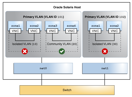
You can configure multiple private virtual networks within a single network unit such as a switch by combining VLANs and Oracle Solaris zones. With PVLAN you can provide network isolation between zones which are in the same VLAN without introducing any additional VLANs. The following figure shows a system with two physical NICs and two configured PVLANs, 101 and 102.
Figure 12 PVLAN With Zones

An isolated and a community VLAN are configured on Primary VLAN 101. Only one isolated VLAN is configured on primary VLAN 102. On the Primary VLAN 101, the zones in the isolated VLAN and the community VLAN cannot communicate with each other. However, the zones within the community VLAN can communicate with each other.
For information about how to assign PVLAN to a zone, see Assigning a PVLAN to a Zone.