Additional Campus Cluster Configuration Examples
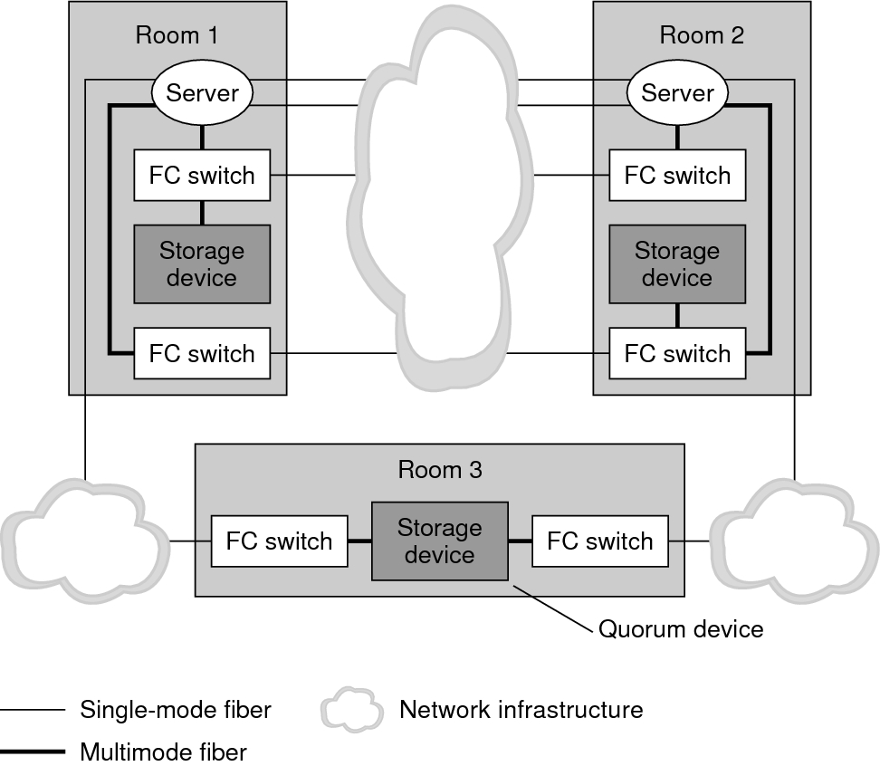
Three-room campus cluster with a multipathing solution implemented (Figure 7–5)
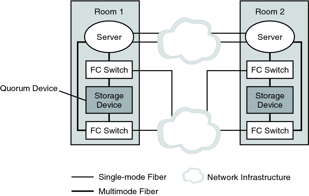
Two-room campus cluster with a multipathing solution implemented (Figure 7–6)
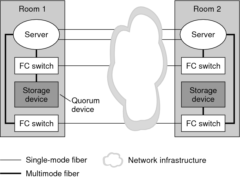
Two-room campus cluster without a multipathing solution implemented (Figure 7–7)
While detailing all of the configurations that are possible in campus clustering is beyond the scope of this document, the following illustrations depict variations on the configurations that were previously shown.
Figure 7-5 Three-Room Campus Cluster With a Multipathing Solution Implemented

Figure 7–6 shows a two-room campus cluster that uses partner pairs of storage devices and four FC switches, with a multipathing solution implemented. The four switches are added to the cluster for greater redundancy and potentially better I/O throughput. Other possible configurations that you could implement include using Oracle's Sun StorEdge T3 partner groups or Oracle's Sun StorEdge 9910/9960 arrays with Oracle Solaris I/O multipathing software installed.
For information about Solaris I/O multipathing software for the Oracle Solaris 11 OS, see the Managing SAN Devices and Multipathing in Oracle Solaris 11.2 .
Figure 7-6 Two-Room Campus Cluster With a Multipathing Solution Implemented

The configuration in the following figure could be implemented by using Oracle's Sun StorEdge T3 or T3+ arrays in single-controller configurations, rather than partner groups.
Figure 7-7 Two-Room Campus Cluster Without a Multipathing Solution Implemented
