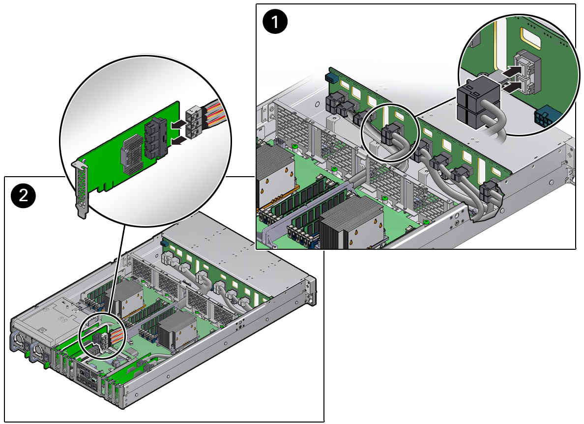
Install NVMe Cables
-
Install the NVMe cables between the front storage drive backplane and the
Oracle PCIe NVMe switch cards in the storage server PCIe slots.
Note - NVMe cable connectors do not fit through the left-side chassis mid-wall. If you are installing NVMe cables between the disk backplane and PCIe slots 5 and 6, you first must remove the chassis mid-wall. For instructions, see Step 3 in Install the Motherboard Assembly.- For Oracle PCIe NVMe switch cards located in PCIe slots 1 and 2, route the NVMe cable bundle through the center chassis mid-wall and via the cable trough between the fan modules and processors.
- For Oracle PCIe NVMe switch cards located in PCIe slots 5 and 6, route the NVMe cable bundle through the left-side chassis mid-wall and along the left side of the chassis.
-
Reconnect the twelve NVMe cables to the front storage drive backplane
[1].
Plug each cable into its connector until you hear an audible click.

-
Reconnect the twelve NVMe cables to the Oracle PCIe NVMe switch cards in PCIe
slots 1, 2, 5, and 6 [2].
Plug each cable into its connector until you hear an audible click. See also Install a PCIe Card.
Use the following table to ensure proper NVMe cable connections.
Note - Each NVMe cable contains a matching label that corresponds to the port on the Oracle PCIe NVMe switch card and the storage drive backplane connector. PCIe NVMe switch card ports are labeled 0, 1, 2, and 3 (from bottom to top). Port 3 is not used.PCIe Slot to BackplanePCIe NVMe Switch Card PortStorage Drive Backplane ConnectorPCIe slot 1 to right side disk backplane0D1E2FPCIe slot 2 to right side disk backplane0A1B2CPCIe slot 5 to left side disk backplane0D1E2FPCIe slot 6 to left side disk backplane0A1B2C -
Return the storage server to operation.
- Install the storage server's front fan assembly door.
-
Install the fan modules.
See Install a Fan Module.
-
Install the air baffle.
Install the air baffle by placing it into the storage server and lowering it to its installed position.
- Install the storage server top cover.
- Return the storage server to the normal rack position.
-
Reconnect the power cords to the power supplies, and power on the storage
server.
See Reconnect Power and Data Cables and Power On the Storage Server. Verify that the power supply AC OK LED is lit.
- Verify that NVMe cable connections are correct. See Verify NVMe Cable Connections.