
You specify settings on the Location window to configure Corente Services Gateways.
The Location tab captures basic information regarding your new site.
Identity and Location
This section captures information regarding the name and physical location of your new site.
Location Name: Enter the alphanumeric identifier for the Location that you are creating. This name must be unique within your domain. This name cannot be changed once you complete this form, so choose carefully. This will be the name used at all times to identify this Location, and will be assigned as the actual computer name of the Corente Services Gateway when it is booted with the configuration file that you are currently preparing. If you choose a name that is a valid NetBIOS name (i.e., 15 characters or less), users can connect to the Location to access remote computers on the domain using this name instead of the IP address.
Street Address: Enter the street address of the new Location that you are creating. This address can be up to 100 alphanumeric characters.
City: Enter the name of the city where this Location will be located. You may use up to 30 alphanumeric characters for this field.
State/Province: Select the appropriate state or province from the pull down list provided.
Postal Code: If applicable, enter the 5 digit U.S. postal code for the location of this Location. The initial placement of your Location icon on the U.S. map will be determined by this zip code. If you do not enter a valid code in this field, the icon will be placed in the upper right hand corner of the map.
Country: Select the appropriate country from the pull down list provided.
Time Zone: Select the appropriate time zone for the Location from the pull down list provided.
Maintenance
This section captures information regarding the upgrade preferences for this Location.
Require Administrator approval to enable Partner connections: By checking the box, you will require that the Corente Services Gateway is approved by an administrator before it is fully operational. When this option is selected for a new Corente Services Gateway and the configuration file for the Corente Services Gateway is downloaded, the new Location gateway is active but unable to connect to any of its partners. However, it is in communication with the Corente SCP while it waits for approval, so that connection to its partners can begin immediately following approval. The gateway icon is marked with a black triangle to signify that approval is required.
To approve the Corente Services Gateway, an administrator must right-click the Corente Services Gateway's icon in App Net Manager and select Approve Partner Connections. The Approve Partner Connections window will be displayed. Enter your login password and click Approve to approve the connections. Approval will be required again if the configuration is ever regenerated and re-downloaded. By leaving the box unchecked, the Corente Services Gateway will become operational and connect to its partners immediately following configuration download.
Automatic reboot after maintenance: Leave this box selected if you would like your Corente Services Gateway to automatically reboot after maintenance has been performed. If this box is selected, be aware that a reboot will pause your network connections until the operation is complete. If you unselect this box and your software has been upgraded, you will have to manually reboot the Corente Services Gateway in order for the machine to switch to the upgraded software. By default, this option is selected.
Preferred maintenance time: Upgrades to new versions of the Corente Services Gateway software will occasionally be downloaded automatically to your Location gateway from the Corente SCP. Select a day of the week and an hour when your network is least busy so that it can be interrupted for these upgrades safely, without harm to your business.
Remote Logging
This section allows you to specify a server that will capture log messages from the Corente Services Gateway. These options require the logging server to be configured appropriately to accept a syslog feed.
System Logging: Select this option to send all system log messages to an external server. The system log is normally recorded on the Corente Services Gateway itself. However, when this option is selected, the Location gateway will track and send all firewall log events to be recorded on the logging server that you specify. This is a traditional firewall log; a message is sent whenever a packet is denied from passing through the Corente Services Gateway. When this option is selected, the Logging Server Address field must be filled in.
Logging Server Address: When system logging is selected, enter the IP address of the logging server in this field. All log messages will be sent to this server.
Redundant Hardware Configuration
This section captures your preferences if you would like to provide redundant hardware for this Corente Services Gateway configuration. Hardware redundancy provides a site with a backup domain connection to use in the event of a hardware or software failure of the site's active Corente Services Gateway. To provide backup, two servers loaded with the Corente Services Gateway software are installed on the LAN. These servers function as a single entity, each alternating between serving as the Active Location gateway and the Standby Corente Services Gateway. You will not be able to choose which Corente Services Gateway is Active and which is Standby; this is negotiated between the pair.
Redundant hardware requires each participating Corente Services Gateway server to have an additional, dedicated Ethernet interface. (This means that Corente Services Gateways using the Peer configuration must have at least two Ethernet cards, and gateways using the Inline configuration must have at least three Ethernet cards.) The two gateways will be connected via these Ethernet interfaces. You can do this using either a VLAN on a router or a dedicated hub. The Ethernet interfaces for the two Location gateways will be on their own subnet (1.1.1.1/30).
The Active and Standby Corente Services Gateways require only one configuration file to be used between them. The Location gateways must both be connected to the LAN and to the same Internet Access Device, and share a set of IP address(es) and MAC address(es) for their LAN and WAN (or LAN/WAN) interface(s). The configuration file must be manually installed on the first Corente Services Gateway. Make sure a monitor/keyboard or is connected to this server. Also ensure that the router or hub to which the two Locations gateways will connect is turned on. When the first Corente Services Gateway reboots, the installation interface will ask to identify the MAC address of the backchannel port being used for redundant hardware:
"This is to configure the backchannel network interface port for the hardware
failover. Now please disconnect all network cables to this gateway machine.
Identify the network port that is dedicated to the hardware failover. Using a cable,
connect the dedicated port to a hub, switch, or an active network device. Make sure
you see the 'link' light of the network port is on. Select 'Continue' to continue with
the Backchannel Configuration."
After following these directions, make sure both servers are connected to the LAN, hub or router, and have access to the Internet. Next, the software should be loaded onto the second server. Make sure a monitor/keyboard is connected to this server. This server will reboot, and the Failover Configuration option must be selected on the installation interface. The configuration will then load onto the second server, and the installation interface will ask to identify the MAC address for this server as well.
If you have enabled the Dual WAN feature on the Network tab, you will be unable to enable hardware failover.
When a software upgrade occurs (during the maintenance window that you scheduled above), the Corente Services Gateway hardware that is currently Active will be upgraded first. Once the upgrade has completed, the hardware will alternate and the Standby Location gateway will become Active so that it can be upgraded as well. This may cause multiple upgrade and tunnel up/tunnel down alerts, because the Corente Services Gateway that is upgraded first will attempt to re-establish its tunnels before the hardware switch occurs. Before it becomes the Standby Corente Services Gateway, it will bring the tunnels down again. Once the second Corente Services Gateway has completed the upgrade, it will establish the tunnels and remain as the Active Corente Services Gateway until the next hardware switch occurs.
Enable Redundant Hardware configuration: Select this option to enable hardware redundancy. If this option has been enabled, the following additional options will be available:
Enable scheduled hardware switch during weekly maintenance window: Select this option if you would like the Corente Services Gateways to rotate weekly between which Corente Services Gateway is designated as the Active and which as the Standby, so that each piece of hardware can be regularly confirmed to be functioning correctly. This switchover will occur during the weekly Preferred maintenance time that you specified above.
The following settings allow you to specify the timing of the failover intervals:
Redundant Hardware Keep-Alive Interval (seconds): The interval of time between each "heartbeat packet" that is sent by the Standby Corente Services Gateway to the Active Corente Services Gateway to make sure that the Active Corente Services Gateway is still functioning. The default is 60 seconds, with a maximum of 600 seconds.
Failover Interval after loss of Keep-Alive (seconds): The period of time that the Standby Corente Services Gateway will wait to initiate failover if the Active Corente Services Gateway has not responded to its "heartbeat" packet. This variable must be set at least twice the amount of time as the Redundant Hardware Keep-Alive Interval; therefore, the default is 120 seconds, with a maximum of 1200 seconds.
Every 10 attempts, the Redundant Hardware Keep-Alive Interval will be doubled, maxing out at 600 seconds. If this makes the interval longer than the Failover Interval after loss of Keep-Alive, then that interval will be doubled as well, maxing out at 1200 seconds. Upon success (or a restart after a failover), both intervals will revert back to the initial configured time.
Cloud Failover
The Cloud Failover section is available if you use a supported third-party VPN device configuration and applies only in the Oracle Public Cloud environment.
Failover Location Address: Specifies the LAN IP address of the Corente Services Gateway you plan to use as a failover location. In the event that the IPSec tunnel to the third-party device becomes unavailable, the Corente Services Gateway forwards packets to the failover location. The failover occurs within 30 seconds.
The following diagram illustrates the cloud failover configuration:
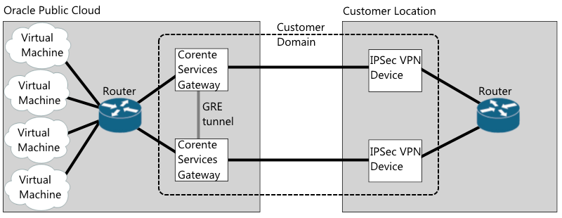
The preceding diagram shows two Corente Services Gateways that reside on the Oracle Public Cloud network and two third-party VPN devices that reside on the customer network. You configure the Corente Services Gateways and the third-party VPN devices on the same domain in App Net Manager. The two Corente Services Gateways are not partners. You partner each Corente Services Gateway with one of the third-party VPN devices.
In a cloud failover configuration, Corente Services Gateways:
Must have an inline configuration.
Must have the same LAN configuration. Although Corente Services Gateways do have different LAN IP addresses.
Must have the same User Group configuration.
You must enable dead peer detection (DPD) for the third-party VPN devices and ensure that they have the same subnet configuration.
Zero Touch Configuration
This section captures your preferences for Zero Touch Installation, which allows you to install a new Corente Services Gateway simply by placing a server loaded with the gateway software on the network and turning it on. When installing a new Location gateway, the configuration file is downloaded upon the first reboot after software installation. If there is no configuration file found on a floppy, a USB, or on the hard drive, the new Corente Services Gateway will attempt to acquire a dynamic IP address via DHCP.
To utilize Zero Touch Installation, the Corente Services Gateway
must be able to connect to the Internet, and the DNS server
must be able to resolve www.corente.comto
the Corente SCP. Communication between the new
Corente Services Gateway and the Corente SCP is secured
using the HTTPS protocol.
Zero Touch Installation cannot be used when the following IP addressing options are used for the WAN (Inline configuration) or WAN/LAN (Peer configuration) interfaces of the Location gateway:
Static IP address
PPoE
Proxy Server
These options may be used for normal operation of the Location gateway, however they cannot be used to download the configuration via Zero Touch Installation.
Fill out the fields as follows:
Enable Zero Touch Configuration: Select this option to enable Zero Touch Configuration.
Unique Identifier: Enter the unique identifier for the Corente Services Gateway server. You need only enter one unique identifier: either a service tag or a MAC address of one of the Corente Services Gateway's Ethernet interfaces. The software reads the service tag and all MAC addresses from the Corente Services Gateway server and passes all of them to Corente SCP, which then matches the identifier with the appropriate configuration file.
Notes
This field allows you to save notes about this Location that can be viewed by other administrators of the domain. You can enter up to 250 characters.
Advanced Performance Tuning
You can disable the options in this section to improve the throughput of the gateway by suppressing potentially compute-intensive side processes.
Enable Probe Monitoring (Security): Select this option to enable the Location gateway to determine if hostile network probing is occurring through the network. When deselected, probe monitoring is disabled and notifications will not be sent.
Enable Report Data Collection: Select this option to enable the collection of data for reports and graphs, such as bandwidth reports. When deselected, the gateway does not collect and present this data in App Net Manager.
Enable Compression: Select this option to enable compression for IPSec connections. Turning compression off on high-speed links results in better throughput performance. By default, compression is disabled for a new Location.
The Network tab captures the following network-specific IP address information:
This section enables you to modify the network addresses that were assigned to the Ethernet interfaces of this Location gateway. All addresses that have been defined for the Ethernet interfaces of the Corente Services Gateway are listed in the table in this section.
To add a new network interface to this list, select the Add button. You can also Edit or Delete an existing interface. When Add is selected, you must select the type of configuration that your Corente Services Gateway will use and the interface that you want to define.
Peer Configuration
The Peer configuration is a Corente Services Gateway with a single Ethernet interface. The Peer Corente Services Gateway is added to an already existing LAN consisting of the machines that will be participating in the application network. It requires additional routing or server configuration to ensure that packets destined for a partner Location get routed to the local Corente Services Gateway first.
If your Corente Services Gateway is a Peer, select the WAN/LAN interface option and click OK to add or edit the interface.
Addressing and DNS: You supplied your addressing and DNS preferences using the Location Wizard. These preferences are shown in this window, but can be changed at any time.
GRE Tunnels: This window enables you to configure use of a GRE (Generic Routing Encapsulation) tunnel for the LAN. Select the Use GRE Tunnel checkbox and enter the IP address for the tunnel.
IP addresses in the 10.x.x.x range are not supported for GRE tunnels.
Proxy Server: This window enables you to indicate whether or not a proxy server is installed between this Corente Services Gateway and the Internet. There are two types of proxy supported, SOCKS and Web.
Internet Access via Proxy Server: Check this box if your Location gateway connects to the Internet from behind a proxy server.
Proxy Type: In the drop-down list, select SOCKS or Web. Select SOCKS if your proxy server provides SOCKS V4/V5 server support in order to interoperate with the Corente Services Gateway. When this is selected, the Proxy IP Address and Port fields will be enabled and must be filled in. If the proxy server is a web proxy, select Web and the Proxy IP Address and Port fields will be enabled and must be filled in.
Proxy IP Address: If you check Internet Access via Proxy Server, enter the IP address of the proxy server that your Corente Services Gateway operates behind. Even if your Corente Services Gateway is a DHCP client, you must determine the address of the proxy and enter it here.
Proxy Port: If you check Internet Access via Proxy Server, you must enter the port number that your proxy server uses. This must be specified to allow the automatic Corente Services Gateway software updates to occur on your Corente Services Gateway. The default port is 80, which is used by most proxy servers.
Additional configuration is required when your LAN includes a proxy server. You must make sure that all the computers on the same subnet as your Corente Services Gateway change the settings of their web browser to bypass the proxy server for local addresses and to specifically exclude the IP Address of the Corente Services Gateway.
Similarly, if you need to access the App Net Manager from a computer operating behind a proxy server, you must exclude the address of this application in your browser as well.
For example, if you are using Internet Explorer and you are operating behind a proxy server:
Select the Tools menu and choose Internet Options.
In the new window that opens, select the Connections tab.
Click the LAN Settings button when it appears. Make sure that the Use a proxy server checkbox is marked.
Enter the LAN IP Address and port number of the proxy server in the fields provided, and then make sure that the Bypass proxy server for local addresses checkbox is selected.
Click the Advanced... button right next to these fields and enter the IP Address of your Corente Services Gateway in the Exceptions list. Traffic destined for App Net Manager at
https://www.corente.com/appnetshould not be routed to the proxy server, either. If you are granting access to the App Net Manager application, enter the addresshttps://www.corente.com/appnetinto the Exceptions list as well.Click OK twice and your browser settings will be stored.
This process must be performed on each computer’s web browser in order for the computers to access the Corente Services Gateway and application network.
DHCP Servers: This window enables you to configure the Corente Services Gateway DHCP server that can distribute IP addressing information to computers on the Corente Services Gateway’s LAN, as well as to its Corente Client partners. click the LAN DHCP Server Configure button.
Interface Aliases: This window enables you to assign alias addresses to the LAN/WAN interface of the gateway. Alias addresses are used with the port forwarding feature, which directs traffic from the Internet/WAN through the gateway to servers on the LAN or in the DMZ.
Inline Configuration
The Inline configuration is a Corente Services Gateway with two Ethernet interfaces. One Ethernet interface is connected to the internal local area network (LAN). The other interface is connected to an external interface, which is typically the Internet access device for that location. All traffic must pass through the Corente Services Gateway in order to reach into and out of the internal local network.
If your Corente Services Gateway is an Inline, you must configure both a LAN and a WAN interface. You also have the option of configuring a secondary WAN interface, if you would like to use the Dual WAN feature, or a DMZ interface, if you will be using your Corente Services Gateway to implement a DMZ.
Addressing and DNS: You supplied your addressing and DNS preferences for both the LAN and the WAN interfaces in the Location Wizard. These preferences will appear each interface’s window, but can be changed at any time.
GRE Tunnels: This window enables you to configure use of a GRE (Generic Routing Encapsulation) tunnel for the LAN. Select the Use GRE Tunnel checkbox and enter the IP address for the tunnel.
IP addresses in the 10.x.x.x range are not supported for GRE tunnels.
DHCP Servers: The Edit LAN Interface window enables you to configure the Corente Services Gateway DHCP server that can distribute IP addressing information to computers on the Corente Services Gateway’s LAN, as well as to its Corente Client partners. Click the LAN DHCP Server Configure button.
Proxy Server: In addition to assigning addressing information, this window enables you to indicate whether or not a proxy server is installed between this Corente Services Gateway and the Internet. There are two types of proxy supported, SOCKS and Web.
Internet Access via Proxy Server: Check this box if your Location gateway connects to the Internet from behind a proxy server.
Proxy Type: In the drop-down list, select SOCKS or Web. Select SOCKS if your proxy server provides SOCKS V4/V5 server support in order to interoperate with the Corente Services Gateway. When this is selected, the Proxy IP Address and Port fields will be enabled and must be filled in. If the proxy server is a web proxy, select Web and the Proxy IP Address and Port fields will be enabled and must be filled in.
Proxy IP Address: If you check Internet Access via Proxy Server, enter the IP address of the proxy server that your Corente Services Gateway operates behind. Even if your Corente Services Gateway is a DHCP client, you must determine the address of the proxy and enter it here.
Proxy Port: If you check Internet Access via Proxy Server, you must enter the port number that your proxy server uses. This must be specified to allow the automatic Corente Services Gateway software updates to occur on your Corente Services Gateway. The default port is 80, which is used by most proxy servers.
Additional configuration is required when your LAN includes a proxy server. You must make sure that all the computers on the same subnet as your Corente Services Gateway change the settings of their web browser to bypass the proxy server for local addresses and to specifically exclude the IP Address of the Corente Services Gateway.
Similarly, if you need to access the App Net Manager from a computer operating behind a proxy server, you must exclude the address of this application in your browser as well.
For example, if you are using Internet Explorer and you are operating behind a proxy server:
Select the Tools menu and choose Internet Options.
In the new window that opens, select the Connections tab.
Click the LAN Settings button when it appears. Make sure that the Use a proxy server checkbox is selected.
Enter the LAN IP Address and port number of the proxy server in the fields provided, and then make sure that the Bypass proxy server for local addresses checkbox is selected.
Click the Advanced... button right next to these fields and enter the IP Address of your Corente Services Gateway in the Exceptions list. Traffic destined for App Net Manager at
https://www.corente.com/appnetshould not be routed to the proxy server, either. If you are granting access to the App Net Manager application, enter the addresshttps://www.corente.com/appnetinto the Exceptions list as well.Click OK twice and your browser settings will be stored.
This process must be performed on each computer’s web browser in order for the computers to access the Corente Services Gateway and application network.
Interface Aliases: The Edit WAN Interface screen enables you to assign alias addresses to the WAN interface of the gateway. Alias addresses are used with the port forwarding feature, which directs traffic from the Internet/WAN through the gateway to servers on the LAN or in the DMZ.
WAN Secondary Interface
The Dual WAN feature allows customers to set up WAN failover for a Corente Services Gateway from a primary WAN connection to a secondary WAN connection, to ensure continued access to the secure Corente Services network and Internet in the event of a WAN failure. After failover, the gateway will detect when the primary WAN connection has recovered and will automatically failback. Note that this feature does not currently support load balancing across the two WAN connections.
The Dual WAN feature can be used with a Corente Services Gateway in the Inline configuration that contains at least three Ethernet cards. One Ethernet card is for the LAN connection, one is for the primary WAN connection, and one is for the secondary WAN connection.
Dual WAN cannot be enabled on a gateway that is using the following features:
Hardware failover.
WAN interface alias addresses for port forwarding on either the primary WAN interface or secondary WAN interface.
If you plan to enable Dual WAN for gateway already in use, it is recommended that you perform a new installation of the Corente Services Gateway Software and personality file on your hardware due to several specific installation steps that are required. In particular, ensure that the gateway to which you are adding this feature is turned off before starting installation of the personality file.
To configure the secondary WAN interface, select WAN Secondary Interface on the Add Network Interfaces dialog box. In the Addressing section on the window that appears, select how an IP Address, Subnet Mask, and Default Gateway will be assigned to this secondary WAN interface.
DHCP: Select this option to allow a DHCP Server to automatically assign an IP Address, Subnet Mask, and Gateway address to the secondary WAN interface of this gateway.
Static: When this option is selected, you must manually enter addressing information for this interface.
PPPoE: Select this option if your gateway will use PPPoE to connect to the secondary WAN connection from this interface.
In the WAN Failover section, fill out the field as follows:
Failover/Failback detection interval: Enter the period of time (in seconds) that the gateway will wait before an outage of the primary WAN connection causes a failover to the secondary WAN connection. Once the primary WAN connection comes up again, failback will be delayed for the same interval or 300 seconds, whichever is less. This ensures that the primary WAN connection is operational and prevents flapping of the interface. The default failover interval is 600 seconds, but can be between 30 seconds and 86,400 seconds (24 hours). The default failback interval is 300 seconds, but will use the same interval you have set for the failover interval, up to a maximum of 300 seconds. Note that failover and failback will each cause a restart of the gateway service (but not of the gateway hardware itself).
After installing (or reinstalling) the Corente Services Gateway software onto your gateway, make sure the gateway hardware is turned off. Connect the Ethernet cable for the primary WAN to one of the gateway’s Ethernet interfaces. It does not matter which Ethernet interface this cable is plugged into, as the gateway will itself designate that particular interface as the primary WAN interface. Do not connect the secondary WAN connection to an Ethernet interface yet.
Once the gateway has started up and connected to the Corente SCP over the primary WAN connection, connect the Ethernet cable for the secondary WAN connection to an Ethernet interface of the gateway. You should then access the Control page of Gateway Viewer and force a failover to the secondary WAN connection to ensure that it is working.
After you add a WAN Secondary Interface, the interface identified as WAN Interface will function as the primary WAN interface.
Enable Alias Addresses for Port Forwarding
Normally, a Corente Services Gateway prevents access to the LAN from the Internet/WAN, allowing external connections only from partner Locations or Corente Clients. But your corporate network may contain servers that must be reachable by Internet/WAN traffic. For example, a web server that serves your company’s website. Port forwarding allows these servers to use the gateway’s LAN/WAN or WAN interface as their own public interface, with the gateway filtering out the unwanted traffic and passing on only the approved type of traffic to the designated server.
Specifically, port forwarding allows an administrator to forward traffic bound for particular ports of the gateway’s LAN/WAN or WAN address to the appropriate servers behind the gateway. For example, port forwarding can be configured so that all traffic pointed at the gateway’s WAN address and port 80, the standard port used for HTTP traffic, is forwarded by the gateway to a web server in your DMZ.
If multiple DMZ servers will need to utilize the same port, an administrator can create multiple alias addresses for the gateway’s LAN/WAN or WAN interface and ensure that all incoming traffic through the gateway to that alias address is forwarded to specific servers on the private LAN of the DMZ. Aliases are used, for example, when you have two web servers in your DMZ that both use HTTP on port 80. One server can use the LAN/WAN or WAN address of the gateway as its routable address, but each additional server using port 80 will require a distinct routable address to ensure that traffic is routed appropriately. The addresses that you use as aliases must be routable addresses that are otherwise not in use.
To configure alias addresses, edit the LAN/WAN or WAN interface of the Corente Services Gateway. Click the Add button in the Interface Aliases section.
Fill out the fields as follows:
Interface Alias Name: Enter a name for this alias. This name will be used for administration purposes in App Net Manager.
Alias IP Address: Enter the alias IP address for the interface. The address that you enter here must be a routable address that is otherwise not in use.
Click OK to save the alias. The alias will now be listed in the Interface Aliases section.
Click OK again when you have finished adding alias addresses. You will use the aliases you have entered to forward traffic from the gateway to the appropriate servers via tube definitions for the DMZ to Internet Access partner or LAN to Internet Access partner on the Partners tab of the Location form.
Port forwarding and aliases are not necessarily used only with a DMZ. They can also be used whenever you have multiple servers using the same port and you would like them all to be reachable from the Internet/WAN. These multiple servers may not reside in your DMZ, but directly on your LAN.
Backhaul is a feature that enables you to aggregate all of your application network locations' Internet traffic and have it exit outbound to the Internet and enter inbound to your network via either a single location, or multiple locations. Backhaul requires at least two active Locations in your Corente Services domain. One must be designated as a Backhaul Server and the other as a Backhaul Client.
A Corente Services Gateway that is administered as a Backhaul Client will encrypt all Internet traffic and send it to a Corente Services Gateway designated as a Backhaul Server. The Backhaul Server will route Internet traffic from these Locations to the Internet. This traffic will be routed through whatever devices exist on the Backhaul Server’s network to filter Internet traffic. All application network traffic will continue to use the appropriate tunnels for each partner.
No Backhaul: This Location will not participate in backhaul. This is the default setting for backhaul.
Backhaul Client via server: If you select this option, you must select a Backhaul Server from the selection box beside this option. All Internet traffic for this gateway's LAN will be routed to and from the selected Backhaul Server. Routers behind this Corente Services Gateway will need to be modified to send all outgoing Internet packets to the Corente Services Gateway. The Corente Services Gateway will then send the packets to the gateway designated as the Backhaul Server.
Backhaul Server: This will be a Location to which the Locations designated as Backhaul Clients will send and receive Internet traffic.
Optional Default Gateway: When the Backhaul Server option is selected, you can supply an IP address or DNS name of a server that this Corente Services Gateway will send all of the Internet traffic that has been routed to it. This enables you to specify the server that the traffic will be sent to for filtering and other such services, so that you do not have to change the default Internet Gateway for this gateway in the Network Interfaces section of the Section 11.9.2, “Network Tab”.
If you enable Backhaul, it is important to define a Special Internal Network Description User Group on the User Groups tab that includes all IP addresses on the corporate network. This will allow the Corente Services Gateway to distinguish between the Internet, subnets participating in the application network, and subnets not participating in the application network, so that traffic will not have the opportunity to be routed to the wrong location and create a security risk. For example, if a Special User Group is not defined, a Corente Services Gateway designated as a Backhaul Server might route non-application network traffic from a Backhaul Client to one of its own non-participating subnets, mistaking the subnet's address as part of the Internet.
If a subnet behind a Corente Services Gateway is on a public, world-routable public IP address space, then NAT must occur some place outside the Corente Services Gateway at the Backhaul Server site. If NAT does not occur, return packets will not flow back through the server and tunnels properly to the subnet.
Routing Information Protocol (RIPv2), Open Shortest Path First (OSPF), and Border Gateway Protocol (BGP) can be enabled on your gateway to automate routing if your LAN is divided into multiple subnets and you would like more than one of these subnets to participate in your Corente Services application network.
RIPv2, OSPF, and BGP are useful in environments where routes to these different subnets are changing dynamically. If you enable RIPv2, OSPF, and BGP, you do not need to add static routes for the subnets on the Routes tab of this Location’s Location form. However, you must have entries on the User Group screen for these subnets so that the machines on the subnets can participate in the application network. You must also make sure that there are routers on your local network that know about these subnets and you must configure the routers to respond to RIPv2, OSPF, and BGP.
RIPv2
RIPv2 is a protocol widely used for routing traffic. It is an interior gateway protocol (IGP), which means that it performs routing within a single autonomous system, such as the local area network (LAN). RIPv2 works by sending routing-update messages to computers on the LAN at regular intervals and whenever the network topology changes. RIPv2 identifies how routing on a network has changed by measuring the hop of a RIPv2 packet from its source to its destination. Each hop in a path from source to destination is noted and distributed. When a computer receives a RIPv2 routing-update that includes changes to an entry, it updates its routing table to reflect the new route.
The Corente Services Gateway will support RIPv2 multicast and unicast messages without authentication. The Corente Services Gateway does not support RIPv1 broadcast messages.
To enable RIPv2 on a gateway;, the RIP section on the Section 11.9.2, “Network Tab” of the Location form must be completed as follows:
Enable Routing Information Protocol (RIPv2) on LAN: When this option is selected, the Corente Services Gateway will use RIPv2 to announce routes on the LAN that can used to reach remote application network subnets.
Use non-standard default weight for RIP: To use a non-standard default weight for RIPv2, select this option and enter the weight in the field provided. The default weight is 1. Valid values for this option are 1 to 16. All RIP routes will be assigned this weight.
The Corente Services Gateway implementation of RIPv2 complies with RFC 2453.
OSPF
Open Shortest Path First (OSPF) is a protocol that, like RIPv2, is used for routing IP traffic. It is a link-state protocol. A link can be considered an interface on the router, and the state of the link is a description of that interface and of its relationship to its neighboring routers. The collection of all these link-states forms a link-state database. OSPF uses a link-state algorithm in order to build and calculate the shortest path to all known destinations.
The Corente Services Gateway will support OSPF multicast messages. The Corente Services Gateway can accept unicast messages from routers, but will multicast the responses.
To enable OSPF on a gateway, the OSPF section on the Section 11.9.2, “Network Tab” of the Location form must be completed as follows:
Enable OSPF on LAN: When this option is selected, the Location gateway will use OSPF to announce routes on the LAN that can used to reach remote application network subnets.
Route Cost: To change the cost of routes advertised by OSPF on the gateway, enter a new value in this field. The default cost is 1.
ASN Number: The default ASN number is 0. If you would like, you can enter a new value in this field.
The Corente Services Gateway implementation of OSPF complies with RFC 2328.
BGP
Like RIP and OSPF, Border Gateway Protocol (BGP) is a protocol that is widely used for routing IP traffic. BGP is especially useful in very large private IP networks where routes to these different subnets are changing dynamically. In general, it is more secure than RIP or OSPF, as it reduces the risk of middle man attacks by requiring that you specifically identify routing neighbors of the Corente Services Gateway rather than relying on them to announce themselves.
Enable BGP on LAN: When this option is selected, the Corente Services Gateway will use BGP to announce routes on the LAN that can used to reach remote application network subnets.
AS Number: Enter the AS number of the LAN on which this Location gateway is installed.
Password: Enter the password that the Corente Services Gateway will use when receiving BGP packets from its neighbors.
Neighbors: This Corente Services Gateway's current BGP routing neighbors are listed in this table. When you enable BGP, you must add at least one neighbor in this table. Click Add to add a new neighbor, Edit to edit an existing neighbor, or Delete to remove an existing neighbor.
On the screen that is displayed, enter the IP address of the BGP neighbor on the Corente Services Gateway's LAN, the AS number of the other network it routes to, and, if applicable, the password to be used by the Location when sending packets to this neighbor. When you are finished, click OK to store this neighbor. Note that you can enter duplicate neighbor IP addresses in this table if they have different AS Numbers.
Using RIP, OSPF, and BGP on your Corente Services Gateway
RIPv2, OSPF, and BGP can be used simultaneously on the same network, and can both be enabled on your Corente Services Gateway at the same time. They are enabled individually for each Corente Services Gateway.
If RIPv2 and OSPF are enabled, when a tunnel is successfully established to a remote gateway partner, the local gateway will send RIPv2 and OSPF packets to routers on its LAN interface only that announce the most appropriate routes to the tunnel. All computers on a subnet within the LAN will use the same route to access the tunnel and the appropriate subnet on the other side. When tunnels are brought down, the local gateway will send RIPv2 and OSPF packets to routers on its LAN announcing that the routes are no longer valid.
BGP differs from the other protocols in that, when a tunnel is successfully established to a remote Location partner, the local Corente Services Gateway will send BGP packets only to the routers on its LAN interface that are explicitly listed as neighbors, announcing the most appropriate routes to the tunnel. Like RIPv2 and OSPF, all computers on a subnet within the LAN that has a router with BGP enabled and which is also listed as a neighbor of the Corente Services Gateway will use the same route to access the tunnel and the appropriate subnet on the other side. When tunnels are brought down, the local Location gateway will send BGP packets to its neighbors announcing that the routes are no longer valid.
The Corente Services Gateway will use its LAN interface only to send and honor RIPv2, OSPF, and BGP messages from local routers. RIPv2, OSPF, and BGP will not be sent from or honored by the Corente Services Gateway's WAN interface, and will not be sent over or received from application network tunnels and the Internet.
Additionally, the Corente Services Gateway will only advertise routes that can be used to reach remote application network subnets. RIPv2, OSPF, and BGP will not be used to advertise routes from one local subnet to another local subnet. Normally, the Corente Services Gateway will not use RIPv2, OSPF, or BGP to advertise routes that can be used to reach Corente Clients, unless the client is using a private non world-routable IP address. For example, if the gateway connects to the application network from a LAN. The gateway will never advertise routes for a subnet if the reachable address of the Corente Services Gateway falls into that subnet.
Routes advertised from the Corente Services Gateway with RIPv2, OSPF, or BGP will override routes that you have entered on the Routes tab if the weight of the dynamic route is equal to or less than the weight of the static route. If the weight of the dynamic route is greater than the weight of the static route, the static route will be used first. A lower weight gives greater precedence to routes.
If you enable RIPv2, OSPF, and BGP, you do not need to add routes to the subnets on the Routes tab. However, you must have an entry on the User Groups tab for these subnets so that the machines on the subnets can participate in the application network. You must also make sure that there are routers on your local network that know about these subnets and you must configure these routers to respond to RIPv2, OSPF, or BGP messages.
Turning on RIPv2, OSPF, and BGP on your Network Routers
If you plan to use RIPv2, OSPF, and BGP to advertise routes on your multiple subnet LAN, you must turn on RIPv2, OSPF, and BGP on the appropriate network routers. For more information about turning on RIPv2, OSPF, and BGP, refer to the documentation provided with your router.
To prevent the possibility of intruders duplicating one of your Locations and gaining access to your domain, you can enable the Reject WAN Interface Mismatch security feature. If this feature is enabled for a Location and it attempts to connect with the Corente SCP when the IP address or MAC address of its WAN interface or WAN/LAN interface are not the same as the IP address or MAC address that were used the last time the Location was in contact with the Corente SCP, an alarm will be generated and the Location will be denied from contacting the Corente SCP. You should contact Oracle Support if this occurs.
If a WAN Interface mismatch occurs because you moved or swapped the hardware for the Location without selecting the Allow One WAN Interface change option described below, select that option and save your changes to the Location form. This Location will then be allowed to connect to the Corente SCP and function as usual.
Complete the fields as follows:
Reject WAN Interface Mismatch: When this option is selected, if the Location contacts the Corente SCP and the IP address or MAC address of the WAN interface (or WAN/LAN interface) have changed, the Location will be denied from contacting the Corente SCP and an alarm will be generated.
When this option is selected, the following checkbox will be made available:
Allow One WAN Interface Change: If you plan to move or change the hardware for the Corente Services Gateway, select this option first. This allows the new hardware to establish a secure connection with the Corente SCP with its new IP address and MAC address, which will be recorded at the Corente SCP. Once the new IP address and MAC address are recorded, this option will be deselected and the Reject WAN Interface Mismatch feature will function as described above. You must reselect this option the next time you would like to change the hardware.
The Other Settings section captures your preferences regarding nested subnets, remote access to Gateway Viewer, and the session re-key interval.
You can enable any of the following options:
Perform DNS/WINS Fixup: If a computer has name services such as DNS or WINS configured on the system, the name used by the computer to make a connection will be resolved by DNS or WINS. For name resolution, the IP address of a computer that is stored on a DNS or WINS server is usually the computer's real IP address. If NAT occurs between two Corente Services Gateway partners within the application network, computers on one network of the application network will not be able to use the real IP address returned from DNS or WINS to connect to remote computers on the other network.
The problem can be solved with DNS/WINS Fixup. If the Perform DNS/WINS Fixup option is checked, computers behind this Corente Services Gateway will always use the correct IP address to connect to another computer across the application network, either its real or NATed IP address. To provide this service, all packets from DNS/WINS servers within the application network are redirected to the DNS/WINS proxy on the Corente Services Gateway. Every name query response packet is checked and, if necessary, its contents are updated. The final DNS/WINS response packet with correct IP information is then forwarded to the original requester. The fixup is done automatically and is completely transparent to the end users. This feature allows all computers behind the Corente Services Gateway, including Corente Clients, to connect by name to remote NATed computers within the application network, using any application (such as ftp, http, telnet, and ping).
NoteThe DNS/WINS Fixup will work only when name resolution requests are made via the Corente Services Gateway. This means that the DNS/WINS servers cannot reside on the same subnet as the computers using this service. Also, the fixup applies only to DNS/WINS packets within the application network. Therefore, a computer using DNS/WINS servers on the Internet will not benefit from this feature. Computers behind the Corente Services Gateway can have different DNS/WINS configurations as long as the Corente Services Gateway is in the name service request path.
By default, this option is disabled.
Nested Subnets: When you create a User Group for your Location during Location gateway creation in the Location Wizard, or on the User Groups tab, you indicate one or more ranges of IP addresses in your local network that will participate in the application network. Each Corente Services Gateway has one or more User Groups.
By default, the service will not permit ambiguous handling of any IP address. For example, this means that no conflicting rules are permitted where the same IP address exists in a User Group for the local Corente Services Gateway and also exists in a User Group for this remote Location partner.
However, many network administrators make use of the fact that normal IP routing rules are ordered so that a more specific rule applies before a more general one. If there are conflicting rules for certain IP addresses, the rule describing the smaller subnet would take precedence. For example, a central site might have a User Group that includes all of 172.16.0.0/16 and a remote Location partner might have a User Group that includes 172.16.1.0/24. The remote Location partner's User Group description would override the central site's User Group because it contains a more specific range of addresses. Notice that the remote partner's User Group is completely contained inside the central site's User Group. This is what is referred to as a "nested subnet". Address ranges that overlap each other entirely are never permitted between Locations.
When this option is checked, nested subnets as described above will be permitted by this Corente Services Gateway. It is recommended that you do not check this option, as nested subnets can cause routing problems that are difficult to diagnose.
By default, this option will be unchecked for new Location gateways. When this option is unchecked, nested subnets will cause a Configuration Alert and no tunnels will be established between this Location and its partners.
A Configuration Alert for nested subnets can be prevented between two Locations that are partners, if you:
Enter mutually exclusive IP address ranges in the User Groups
Enable Allow Locations to be configured with nested subnets for both Locations
Enable Auto Resolve NAT on both Corente Services Gateways for each other. Auto Resolve NAT is enabled by a Location on a per partner basis. If any conflicts occur between a Location and its partner when Auto Resolve NAT is enabled, the Corente Services Gateway will automatically translate the IP addresses of the partner's User Group to new subnets to prevent the conflicts.)
Compact NAT Subnets: When this option is selected, the Location will sort addresses largest to smallest in order to keep the NAT table to a minimum. This feature applies to both Inbound NAT and Auto Resolve NAT. Locations have this option enabled by default.
Session Re-Key Interval: Session keys are used by a Corente Services Gateway to encrypt the data that is being sent over each of its application network tunnels. A Corente Services Gateway will automatically regenerate its session keys according to the interval that you select with this pull-down menu. The default interval is 8 hours. You may choose a shorter interval,if you prefer.
When you click the LAN DHCP Server button on the Add Interface window, the Edit LAN DHCP Server window will be displayed.
Select the Enable LAN DHCP Server option and fill out this window as follows to configure how DHCP leases are served to computers on the Location's LAN:
DNS Suffix: If you would like, enter a DNS suffix to be served to LAN computers by DHCP. When these computers submit a name for DNS name resolution, this DNS suffix will be appended to that name.
Serve DNS with DHCP: This option enables you to select whether or not to pass the DNS Server IP addresses with the DHCP leases. When this box is selected, the computers on your LAN will be passed the DNS server addresses that are on the Section 11.9.2, “Network Tab” of this Location form.
Serve WINS with DHCP: This option enables you to select whether or not to pass WINS Server IP addresses with the DHCP leases. WINS is the network protocol used in Windows networking; the computer names you see in Network Neighborhood are all resolved into IP addresses, and vice versa, using WINS. When this box is checked, you must enter the IP addresses of the WINS server on your network. These are the addresses that will be passed.
Primary WINS: Enter the IP address of the primary WINS server used to resolve WINS names on your local network.
Secondary WINS: Enter the IP Address of the secondary WINS server that will be used to resolve names if the primary WINS server does not respond. You cannot enter a Secondary WINS address if you have not entered a Primary WINS entry.
Lease expires: If this box is unchecked, the leases that the DHCP server assigns to local computers will be infinite. An address will not change unless the computer reboots. However, if this box is checked, the IP addresses will be temporary assignments. You must then specify in the fields that follow the number of days, hours, and minutes that the addresses should be used. When the specified amount of time is over, the lease is renewed. A lease is also renewed when a computer reboots. The renewed lease may or may not contain the same addresses.
A DHCP Server saves you from the task of manually assigning IP addresses to computers on the Location's subnet. However, each user computer must be configured to obtain IP addresses automatically. In Windows, for example, this can be accomplished easily using the Network option in the Control Panel.
DHCP Address Ranges
When you select the Address Ranges tab in the lower half of the window, this section enables you to create the address pools that will be served by the Location.
The ranges that you create here must correspond with address ranges that are included in the Default User Group on the User Groups tab of this Location’s Location form, to ensure that these computers can participate in the application network.
To begin creating address pools, select the Add button.
On this screen that is displayed, enter the following:
Include Address Range: Select this option to indicate that the entire range you enter here will be served by DHCP.
Exclude Address Range: After defining an Included range, you can exclude certain addresses from that address pool with this option. Enter the range of IP addresses that you would like to exclude from the included range in the Start Address and End Address fields. These addresses will not be served by DHCP. Note that the address of the Corente Services Gateway is automatically excluded and does not need to be entered here.
After selecting Include or Exclude, enter the following:
Start Address: Enter the lowest value of the address range in this field.
End Address: Enter the highest value of the address range in this field. If the range you would like to create contains only one IP address, you do not have to enter anything in this field.
Select the OK button to store this pool. Select Cancel to discard your changes and close the window.
DHCP Reservations
When you select the Reservations tab in the lower half of the window, you can reserve specific IP addresses for machines on the LAN that receive their addressing from the Location's DHCP server.
To begin reserving addresses, select the Add button.
Display Name: Enter a name that will be used to identify this reservation on the App Net Manager interface.
IP Address: Enter the IP address that will be reserved by the Location's DHCP server for use by this machine only. The machine will always receive this address from the DHCP server.
Reserved: When this checkbox is selected, the IP address you entered will be saved and assigned to the machine whenever it receives its addressing via the Location's DHCP server.
MAC Address: If this field is not already filled in, enter the MAC address of the machine for which the reservation is being made. This is how the DHCP server will identify the machine that will receive the reserved IP address.
NetBIOS Name: If the Location has received information from the backend about the machine for which you are reserving an address, this field will display the Net BIOS name of the machine. This field will not accept manual input.
Select the OK button to store this reservation. Select Cancel to discard your changes and close the window.
The Location may receive MAC address information from the backend about clients on the LAN. In that case, those machines will be listed on the table on the right side of the App Net Manager interface when you open the Location in the domain directory, open the Network Interfaces entry, open LAN DHCP Server or RAS Client DHCP Server, and click DHCP Reservations.
Double click any entry in this table and the Edit DHCP Reservation dialog box will be displayed for that machine. Click the Reserved checkbox for this machine to ensure that the machine is served the IP address that you enter on this dialog box every time it receives addressing information from the gateway’s DHCP server.
DHCP Options
When you select the Options tab in the lower half of the window, you can include DHCP options that will be delivered along with addressing information by the Location's DHCP server. These options will be delivered to every device on the LAN that receives its addressing information via DHCP. The receiving device itself will determine whether or not it will use the option string. A typical use for option strings is for configuring handsets for IP telephony.
To begin reserving addresses, select the Add button.
Option Number: Enter the option number that defines this option.
Option String: Enter the string for this option. Only text string options are supported by Corente Cloud Services Exchange. Select the OK button to store this option. Select Cancel to discard your changes and close the window.
The Applications tab enables you to register applications with this location, which can then be shared with any location in your Corente Services network and monitored via the Working with Reports feature of App Net Manager.
You can monitor not only the status and availability of the applications, but also usage, bandwidth, and latency/packet loss statistics per application and per application server.
Corente Cloud Services Exchange application monitoring is designed to be used as follows:
To confirm to both users and administrators that applications are functioning correctly
To facilitate communication between both parties when they are not
To provide reports to help with capacity planning
To provide diagnostic capabilities to locate bad actors within the network.
You can share and monitor any TCP-based application, as well as any of the following types of applications: Email (SMTP, IMAP, and POP), Web (HTTP and HTTPS), Authentication (LDAP), FTP, DNS, and Microsoft File Shares. If the applications you would like to register are not deployed on local servers, the Corente Services Gateway must be able to communicate with the servers either over the Internet or through alternate methods (such as via a private backbone or alternate connection).
The main screen of the Applications tab displays a table of all applications that you have already added.
You may Edit or Delete any application listed in the table.
Select the Add button on the main screen of the Applications tab. The Add Application screen will be displayed.
Complete the following fields and options:
Application: Enter the name of the application as you would like it to appear to users and administrators.
Type: Select the type of application that you are registering with the Location gateway. The following choices are available: Authentication Server, DNS Server, FTP Server, File Server, Generic Server, Mail Server, or Web Server. Select Generic Server when the application you are registering does not fit into the other categories.
Your choice will affect the protocols that you may choose from when you add Application Policies.
Monitoring Enabled: Select this option to enable monitoring of this application. If you do not select this option, this application can be shared with other locations, but will not be monitored via Reports or in Gateway Viewer.
Participates in Secure Network: Select this option to allow this application to be shared over your Corente Services application network. If this option is not selected, you will not be able to share this application like a User Group with other locations. Note that on the Monitoring interface in Gateway Viewer, the application will be listed in the Service Availability Summary section to designate this application as a locally-used application and to differentiate this application from those being shared over the application network, which are listed in the Application Status Summary section.
Notification on Failure: Email: Select this option if you would like the application's administrator to receive an email notification if this application should fail. The notification will be sent to the email address supplied in the Owner Email field. If no email address has been entered that field, the notification will instead be sent to the addresses supplied on the Alerts tab for this Location. .
Owner Email: Enter the email address of the administrator of this application. All email notifications will be sent to this address. Additionally, this email address will be published to any user in Gateway Viewer that has the appropriate permissions to use this application, so that they can communicate directly with the appropriate administrator, if necessary.
Notification on Failure: SNMP: Select this option if you would like to receive an SNMP trap if this application should fail. The SNMP trap will be sent according to the SNMP version and parameters that you specify on the SNMP tab of this Location form.
Host Server Name: Enter the DNS name of the server providing this application.
Host Server IP: Enter the IP address of the server providing this application.
NoteThe following network addresses are restricted and cannot be assigned to any hosts on the LAN:
1.1.1.0
1.1.1.1
1.1.1.2
1.1.1.3
QoS Settings Inbound: If you would like, choose a QoS entry from the pulldown menu to specify the priority of traffic inbound through the Corente Services Gateway to this application. QoS entry definitions in this menu can be viewed or modified with the Section 10.3, “Quality of Service (QoS)” feature.
QoS Settings Outbound: If you would like, choose a QoS entry from the pulldown menu to specify the priority of traffic outbound through the Corente Services Gateway from this application. QoS entry definitions in this menu can be viewed or modified with the Section 10.3, “Quality of Service (QoS)” feature.
NoteAs when performing any sort of QoS configuration, administrators must be careful when assigning QoS levels because if there is too much high priority traffic, any other traffic with a lower level of priority may become too slow or even be dropped. In addition, you cannot use QoS to prioritize traffic to or from a Corente Client.
After providing basic information about the application, you must use the Modify Application Policies section to register the policies of this application. A policy is essentially a combination of protocol and port number that the application's server uses to communicate with the machines that connect with it, or that the machines use to communicate with the server.
The Application Policies table lists all the policies that you have already added. You may Edit or Delete any policy listed in the table. Click Add to create a new policy.
On the screen that is displayed, enter the following:
Protocol: Select the protocol for this policy. The protocols that are available depend on to the Application Type that was chosen for this application.
Port: Enter the port number for this policy.
Direction: Select the direction of the traffic that you are regulating with this policy. For example, traffic that travels in through the Corente Services Gateway to the server, out through the Location gateway from the server, or both.
Administered Application Policy Tests: Application policy tests are tests that are used by the Corente Services Gateway to monitor the application and determine if it is functioning correctly or not. Depending on the test chosen, you will choose thresholds that cause a Warning alarm and a Critical alarm. The types of tests that are available depend on the protocol that you chose for this Application Policy. Each test that you enable will be performed on the application’s traffic once a minute.
The table lists all the tests that you have already added. You may Edit or Delete any test listed in the table. Click Add to create a new test.
On the screen that is displayed, enter the following:
Application Policy Test Name: Select the test you would like to enable from the pull-down menu.
Application Policy Test Arguments: When an Application Policy Test Name is selected, this table lists all of the arguments for that test. To modify the variable for an argument, select the argument and click the blue text in the Variable column. You can enter a new value in the field that is provided.
All Application Types allow you to create policies for ICMP, TCP, and UDP protocols. The following table describes the Policy Tests that you may choose for each of these protocols and what they monitor:
Table 11.1 Policy Tests for ICMP, TCP, and UDP Protocols
Protocol | Test Types | What Test Monitors |
|---|---|---|
ICMP | ICMP PING | This is a standard test that checks the application server for availability. Warning and critical alarms are based on the latency and loss of test packets. |
Roundtrip Latency | This test monitors the average round trip latency of packets sent to and from the applications server. | |
IP Network Quality | This test estimates network quality by measuring a combination of latency, jitter, and packet loss on traffic samples in an interval. The administrator sets acceptable thresholds for latency (in milliseconds) and loss (in percent of packets in the interval). In addition, the length of the jitter buffer (in milliseconds) is also set as the jitter threshold. Each traffic sample is evaluated as acceptable or defective in the following manner:
Administrators can specify or use defaults for: Warning and Critical alarm thresholds based on percentage of defective samples in an interval. Interval in seconds over which the percentage of defective samples will be computed. Acceptability threshold (excess packet loss squared times four plus excess latency). Latency threshold. Jitter threshold. Loss threshold. | |
TCP | ICMP PING | See ICMP PING above. |
Roundtrip Latency | See Roundtrip Telephony above. | |
IP Network Quality | See IP Network Quality above. | |
TCP Connection | This test monitors the TCP connection of the application. | |
UDP | ICMP PING | See ICMP PING above. |
Roundtrip Latency | See Roundtrip Telephony above. | |
IP Network Quality | See IP Network Quality above. | |
UDP Connection | Like the TCP Connection test, but for the UDP protocol. |
In addition to the protocols above, some of the Application Types allow you to create policies for application-specific protocols. In addition to the ICMP PING, Roundtrip Latency, IP Network Quality, and occasionally the TCP Connection test, these protocols each have a protocol-specific test:
Table 11.2 Policy Tests for Application-Specific Protocols
Application Type | Protocol | Test Types | What Test Monitors |
|---|---|---|---|
Authentication Server | LDAP | LDAP Lookup | This test monitors the response time for LDAP packets sent to the LDAP server. |
DNS Server | DNS | DNS Lookup | This test monitors accuracy of the DNS server: you supply a DNS hostname and the IP address that should be returned by the server. In addition, the test monitors the response time and raises a critical alarm when the request has timed out. |
FTP | FTP | FTP Handshake | This test monitors the response time for FTP packets sent to the FTP server. |
File Server | NETBIOS | File Share | This test measures disk usage percentage. You must supply a share name, username, and password to allow the Corente Services Gateway to log onto the File server. |
Mail Server | IMAP | IMAP Handshake | This test monitors the response time for IMAP packets sent to the IMAP server. |
POP | POP Handshake | This test monitors the response time for POP packets sent to the POP server. | |
SMTP | SMTP Handshake | This test monitors the response time for SMTP packets sent to the SMTP server. | |
Secure IMAP | Secure IMAP Handshake | This test monitors the response time for Secure IMAP packets sent to the IMAP server. | |
Secure POP | Secure POP Handshake | This test monitors the response time for Secure POP packets sent to the POP server. | |
Web Server | HTTP | HTTP Transaction | This test monitors the response time of HTTP packets sent to the HTTP server by accessing a specified web page. When an optional Expected Status (string to expect in the first status line of server response) is specified, this test can be used to look for specific HTTP error codes, such as 400. If the string is not found, a CRITICAL alarm is raised. When an optional Expected Expression is specified, the test will search the page returned by the web server for a case-insensitive regular expression. If the specified pattern is not found, a CRITICAL alarm is raised. When an optional Redirection Handling option is specified and the test results in a redirect to another webpage, you can choose to generate no alarm, a WARNING alarm, a CRITICAL alarm, or the redirection can be followed. |
HTTPS | Secure HTTP Transaction | Similar to the HTTP Transaction test, but for HTTPS. |
When you have finished configuring an Application Policy Test, click OK to store your changes or Cancel to close the window and discard your changes. You may add as many tests to an Application Policy as you would like.
When you have finished configuring an Application Policy, click OK to store your changes or Cancel to close the window and discard your changes. You may add as many Application Policies to a monitored application as is required by that application.
When you have finished configuring an Application, click OK to store your changes or Cancel to close the window and discard your changes. The application will be added to the main screen of the Applications tab.
On the Section 11.9.7, “Partners Tab”, you can define permissions by including the applications that you register on this screen in tubes. Tubes allow you to specify a set of remote machines and remote applications that are allowed to communicate with your locally-defined applications, so that you can share these applications with specific computers in any other Location.
The Monitored Servers tab enables you to register servers with this Corente Services Gateway in order to monitor the availability of these servers and the usage of certain resources on these servers, such as CPU, physical memory, disk space, and swap space. You can define thresholds and will be alerted when usage exceeds these thresholds. In addition, all monitored data can be viewed in Gateway Viewer and with the Reports feature.
A Corente Services Gateway uses the Simple Network Management Protocol (SNMP) to monitor servers. Any servers to be monitored must have an SNMP agent installed on them. For Windows servers, the SNMP Windows component is required. For all other operating systems, is is best to use the NET-SNMP agent. But you can use any other agent, as long as it supports the Host Resources MIB as defined in RFC 2790.
You can monitor any server that meets the following requirements:
The monitored server must support SNMP Version 1 (as defined in RFC 1157) and be able to respond to polls from SNMP network management stations.
The monitored server must support the Host Resources MIB (as defined in RFC 2790).
If the monitored server is not on the same LAN as this Corente Services Gateway, the Corente Services Gateway must be able to communicate with the server either over the Internet or through alternate methods (such as via a private backbone or alternate connection).
To monitor a Windows server, you must be logged in as an administrator or a member of the Administrators group. Click Start and go to the Control Panel, double-click Programs and Features, then click Turn Windows features on or off in the left-hand side of the page.
Select the Simple Network Management Protocol check box, and click OK, then click Next.
You may be required to insert the Windows Operating System CD when installing this component.
To configure the SNMP agent, access the Control Panel. Double-click Administrative Tools and then double-click Computer Management.
In the console tree, click Services and Applications and then click Services.
In the details pane, scroll down and click SNMP Service.
From the Action menu, click Properties.
On the Security tab, select Send authentication trap if you want a trap message to be sent whenever authentication fails.
Under Accepted community names, click Add.
Under Community Rights, select a permission level for this host to process SNMP requests from the selected community.
In Community Name, type a case-sensitive community name, and then click Add.
Specify whether or not to accept SNMP packets from a host:
To accept SNMP requests from any host on the network, regardless of identity, click Accept SNMP packets from any host.
To limit acceptance of SNMP packets, click Accept SNMP packets from these hosts, click Add, type the appropriate host name and IP or IPX address, and then click Add again.
Click Apply to apply the changes.
Register the server in the Location form of the local Location gateway.
The main screen of the Monitored Servers tab in the Location form presents a table of all servers that you have already added to be monitored. You may Edit or Delete any server listed in the table.
To add a new server to the table, follow the instructions in Section 11.9.4.4, “Add a New Server for Monitoring”.
Select the Add button on the main screen of the Monitored Servers tab. The Add Monitored Server window will be displayed.
Fill out the fields and options as follows:
Name: Enter the name of the server as you would like it to appear to administrators in Gateway Viewer.
Notify via Email on Failure: Select this option if you would like the server's administrator to receive an email notification if this server reaches its warning or critical thresholds, or if it should fail. The notification will be sent to the email address supplied in the Server Owner Email field. If no email address has been entered that field, the notification will instead be sent to the addresses supplied on the Alerts tab for this Location.
Server Owner Email: Enter the email address of the administrator of this server. If you have selected the Notify via Email on Failure option, all email notifications will be sent to this address.
Type: Select the type of server that you are registering with the Location gateway. The following choices are available: Default (MIB II Host), FreeBSD NET-SNMP, LINUX Net-SNMP, NET-SNMP OS Independent, Solaris NET-SNMP, Windows Server 2008, Windows Server 2012, Windows 10, and Windows Server 2016.
NoteIf your server uses an operating system other than Windows and is using an SNMP agent other than the NET-SNMP agent, you must choose the Default (MIB II Host) server type. Make sure that the SNMP agent you are using on the server supports the Host Resources MIB (aka MIB II Host) as defined in RFC 2790.
Host Name: Enter the DNS name of the server.
Host IP: Enter the IP address of the server.
After providing basic information about the server, you must use the Monitored Server Tests section to register the tests of this application. Server tests are tests that will be performed on the server to identify usage statistics for different resources: CPU load, disk space, memory usage, and swap space. This table lists all the tests that you have already added. You may Edit or Delete any test listed in the table. Click Add to add a new server test.
On the screen that is displayed, enter the following:
Monitored Server Test Name: Choose from four resources that can be monitored: CPU Usage, Disk Usage, Memory Usage, and Swap Usage.
Monitored Server Test Arguments: When a Monitored Server Test Name is selected, this table lists all of the arguments for that test. To modify the variable for an argument, select the argument and click the blue text in the Variable column. You can enter a new value in the field that is provided.
When you have finished defining a server test, click OK to store your changes or Cancel to close the screen and discard your changes. You can enable as many of the tests for a server as you would like. When you have finished defining a monitored server, click OK to store your changes or Cancel to close the screen and discard your changes. Your new monitored server will now appear on the main screen of the Monitored Servers tab.
The User Groups tab lets you identify groups of machines on the local network, such as computers, servers, and printers, that are allowed to participate in your application network.
To begin, you must edit the Default User Group, which provides the Corente Services Gateway with a list of all machines on the LAN that are participating in the application network. You first created this group when you used the Location Wizard to create the Location.
Next, if applicable, you should define your Default User Group – DMZ, which informs the Corente Services Gateway what subnet is designated as the DMZ on your LAN.
Then, you should define the Internal Network Description group, which should contain all of the subnets at your site. This allows the Corente Services Gateway to distinguish between computers on the Internet and computers on the LAN that are not participating in the application network.
After you define these User Groups, you can create additional named User Groups, which will divide the IP addresses on the LAN into smaller groups. Each named User Group consists of machines that will have the same permissions on the domain or LAN. You can create any number of named User Groups for this Location.
On the Section 11.9.7, “Partners Tab” or with the Tube wizard, you can further define and restrict permissions by including your User Groups in tubes. Tubes enable you to specify a set of local machines, a set of remote machines or a remote application, and the firewall policy to be used when these machines communicate.
The following network addresses are restricted and cannot be assigned to any hosts on the LAN:
1.1.1.0
1.1.1.1
1.1.1.2
1.1.1.3
Instead of using the User Groups tab to include application servers on the LAN in your application network, you may want to register these servers on the Section 11.9.3, “Applications Tab”.
The main screen of the User Groups tab displays the User Groups that have already been configured for this Location. Three placeholder User Groups appear by default:
Entire LAN Group: This group is used on the Partners tab exclusively when creating a LAN to Internet Access or LAN to Location Access partnership. It is predefined and cannot be modified.
Location LAN Address: This group is used on the Partners tab when creating a LAN to Location Access partnership or a partnership that allows partners to access the Gateway Viewer application for this Location. It is predefined and cannot be modified.
Default User Group: This group contains every IP address on the LAN that will participate in the application network. It is not predefined and must be configured before a new Location gateway can be installed.
Default User Group - DMZ: (appears only when a DMZ interface has been configured for this Location on the Network tab) This group contains every IP address on the LAN that is participating in the DMZ. Depending on the choices you made when configuring the DMZ interface, this group may or may not be predefined. This group is used exclusively when configuring the DMZ to Internet Access and LAN to DMZ Access partnerships on the Partners tab.
Each Location must have a Default User Group. The Default User Group must contain every IP address on the LAN that will participate in the application network. You created a Default User Group in the Location Wizard when you created your Corente Services Gateway personality, but you can modify this group using the following procedure. To configure the Default User Group, select the Default User Group entry on the main screen of the User Groups tab and select the Edit button. The Edit User Group 'Default User Group' screen will be displayed
On this screen, you must define which computers on the local network will participate in the application network by specifying subnets of IP addresses.
Firewall Policy: If you would like, you can choose an optional Firewall Policy that will apply to all traffic to and from the Default User Group.
Inbound QoS: If you would like, you can choose optional Quality of Service (QoS) settings for traffic inbound to the default User Group. To specify the priority of traffic inbound through the Corente Services Gateway to the default User Group, choose a QoS entry from the Inbound QoS pulldown menu.
Outbound QoS: If you would like, you can choose optional QoS settings for traffic outbound from the default User Group. To specify the priority of traffic outbound through the Location gateway from this User Group, choose a QoS entry from the Outbound QoS pulldown menu.
NoteAs when performing any sort of QoS configuration, administrators must be careful when assigning QoS levels because if there is too much high priority traffic, any other traffic with a lower level of priority may become too slow or even be dropped. In addition, you cannot use QoS to prioritize traffic to or from a Corente Client.
User Group is Within Secure Network: This option will be chosen by default and cannot be changed.
Special Internal Network Description Group: This option will not be chosen by default and cannot be changed.
User Group Subnet/Address Ranges: This section enables you to define the subnets/ranges that you would like to include in the Default User Group. The table lists all the ranges that you have already added. You may Edit or Delete any range listed in the table.
To add a new subnet/range, select the Add button.
Include Subnet: Select this option to specify a range that will be included in the group. Fill out the available fields as follows:
Network Address: Enter the first address of the subnet in this field.
Subnet Mask: Enter the net mask of the subnet in this field, which will define the range of addresses within this subnet.
NoteIf you include a range of IP addresses that is not contained within the same subnet of the LAN IP Address of the Corente Services Gateway or not distributed by the Corente Services Gateway’s DHCP server, you must either provide routing information to this subnet on the Section 11.9.6, “Routes Tab” of this form or enable RIPv2 or OSPF on the Section 11.9.2, “Network Tab” of this form.
Outbound NAT: You must set the appropriate Outbound NAT settings for this subnet. Network Address Translation (NAT) is used to map the real IP address of each machine in a subnet to an IP address within another subnet. The translated IP addresses become the visible IP addresses of the machines. NAT can be used to organize a network or prevent routing problems caused by duplicate IP addresses.
When Outbound NAT is enabled for a Location, the Location gateway will translate the subnet of IP addresses to another subnet before the Corente Services Gateway makes the addresses visible to remote partners. The administrator must specify the new subnet to which the real IP addresses will be translated. Each address within the real subnet will be mapped to an address in the specified subnet. For all remote partners, these specified addresses will become the visible IP addresses of the machines.
The Outbound NAT settings in your User Group will interact with the Auto Resolve NAT and Inbound NAT settings that a Location partner has chosen for your Location.
Prohibited: This setting forbids all partners to perform NAT on this Location’s User Group. If Prohibited has been set on a range in the local User Group and a partner has enabled Auto Resolve NAT (and there is an address conflict) or Inbound NAT for this Location, the tunnel will not be brought up and a Configuration Alert will be generated. In other words, the Prohibited setting will bring down any tunnel to a partner if that partner attempts to NAT this User Group. The primary use for this setting is to prevent NATing on a connection that is transporting a protocol containing embedded IP addresses for which the Corente Services Gateway does not have a fixup module. The Corente Services Gateway includes a fixup module that allows active FTP, normally forbidden on a NATed subnet.
Permitted: This is a passive setting. The Corente Services Gateway will not NAT the address range, but it will not prevent the address range from being NATed by a partner. This is the default setting.
Specified: This setting allows an administrator to specify a new subnet of IP addresses to which this address range will be mapped. The new addresses within the specified subnet will become the visible IP addresses of the local computers in this range to all remote partners. After enabling this option, enter the new subnet in the Specified NAT Address field. This address space must be unique in the application network.
The Specified setting is a useful way of organizing an entire domain, where each User Group in the domain is mapped to a distinct set of address ranges so that there are no address conflicts. The traffic from each site can then be identified by the range into which it has been mapped. Of course, it is the administrator's responsibility to guarantee that there are no conflicts between the addresses that have been Specified for each subnet. Therefore, it is usually preferable to specify Inbound NAT for conflicting addresses (configurable on the Partners tab) rather than use Outbound NAT, because Inbound NAT does not require a global solution and there are no chances for conflicting addresses after the solution has been applied.
Exclude Range: If there are IP addresses or ranges of addresses within the subnets that you have already Included that you do not want to be in your Default User Group, you can use the Exclude Range option to remove these addresses. Select this option to specify a range that will be excluded in the group. Fill out the available fields as follows:
Start Address: Enter the first address of the range that you would like to be excluded from an existing included range.
End Address: Enter the last address of the range that you would like to be excluded from an existing included range. If the range includes only one address, you do not need to fill in this field.
Click OK to add this definition to your Default User Group or Cancel to close the window and discard your changes. Repeat this process for as many subnets as you would like to add to your Default User Group. Remember that you must have at least one IP address listed as an include in the Default User Group even if you are using DHCP. In other words, DHCP is selected for a network interface on the Network tab of this form.
When you are finished defining your Default User Group, click the OK button to store your changes and return to the main User Groups tab.
After defining the Default User Group, you should map out the entire local corporate network, even those computers that are not participating in the application network. You will transfer this information onto your Corente Services Gateway on the User Groups tab, using the Special Internal Network Description User Group option. To configure the Internal Network Description User Group, click the Add button. The Add User Group screen is displayed.
Fill out the screen as described above in the Default User Group section. (Note that you will not be able to select NAT settings for Included subnets.) You must add all subnets within your LAN to this User Group, because this definition includes the entire network, even machines that are not participating in the application network. Select the Special Internal Network Description User Group option and make sure the User Group is Within Secure Network option is not selected.
When you are finished, click the OK button to save your changes and return to the main User Group screen. The Internal Network Description User Group will now be displayed on this screen.
This User Group allows the Corente Services Gateway to distinguish between the corporate network and the Internet, which is especially important when this Corente Services Gateway is acting as a Backhaul Server. It prevents traffic being sent from or received by computers on the LAN that are excluded from the application network for security reasons. For example, if an Internal Network Description User Group is not defined, a Location designated as a Backhaul Server might route non-application-network traffic from a Backhaul Client to one of its own non-participating subnets, believing the subnet's address to be part of the Internet.
After defining the Default User Group, look at your LAN and decide what groups of IP addresses will need similar permissions in your domain and in any of your extranets. This means deciding what remote computers and applications each local computer will need to access or be accessed by, and what protocols must be allowed or denied over their secure connections. Divide your LAN's IP addresses and subnets into groups based on these criteria.
On the User Groups tab, you must configure these groups into named User Groups. You can define as many named User Groups as you need. Named User Groups in a Location can overlap with each other. However, you cannot create two named User Groups that contain the exact same set of IP addresses.
To configure a named User Group, click the Add button. The Add User Group screen will be displayed.
Complete the screen as follows:
User Group Name: Enter a name for this User Group.
Firewall Policy: If you would like, you can choose an optional Firewall Policy that will apply to all traffic to and from this User Group.
Inbound QoS: If you would like, you can choose optional QoS settings for traffic inbound to this User Group. To specify the priority of traffic inbound through the Corente Services Gateway to this User Group, choose a QoS entry from the Inbound QoS pulldown menu.
Outbound QoS: If you would like, you can choose optional QoS settings for traffic outbound from this User Group. To specify the priority of traffic outbound through the Corente Services Gateway from this User Group, choose a QoS entry from the Outbound QoS pulldown menu.
NoteAs when performing any sort of QoS configuration, administrators must be careful when assigning QoS levels because if there is too much high priority traffic, any other traffic with a lower level of priority may become too slow or even be dropped. In addition, you cannot use QoS to prioritize traffic to or from a Corente Client.
User Group is Within Secure Network: Select this option if you would like this User Group to participate in the secure network. This option is selected by default. There are occasionally reasons to create User Groups that are not within the secure application network. Remember that named User Groups within the application network must be subsets of the Default User Group (in other words, they can only include addresses that are also included in the Default User Group).
Special Internal Network Description Group: This option will not be chosen by default and cannot be changed.
User Group Subnet/Address Ranges: This section enables you to define the subnets/ranges that you would like to include in this User Group. The table lists all the ranges that you have already added. You may Edit or Delete any range listed in the table. To add a new subnet/range, select the Add button.
NoteWhen capturing the IP addresses to be included in a User Group, the Include Subnet and Exclude Range options cause the definition of the User Group to differ, as follows:
When all groups of IP addresses in the User Group are specified as Included, the User Group will contain only those IP addresses listed.
When all groups of IP addresses in the User Group are specified as Excluded, the User Group will contain all IP addresses within the Default User Group except for the excluded IP addresses.
When some groups of IP addresses are specified as Included and some as Excluded, the User Group will contain only those IP addresses listed as Includes except for the excluded IP addresses.
Include Subnet: Select this option to specify a range that will be included in the group. Fill out the available fields as follows:
Network Address: Enter the first address of the subnet in this field.
Subnet Mask: Enter the net mask of the subnet in this field, which will define the range of addresses within this subnet.
NoteIf you include a range of IP addresses that is not contained within the same subnet of the LAN IP Address of the Corente Services Gateway or not distributed by the Corente Services Gateway’s DHCP server, you must provide routing information to this subnet on the Routes tab or enable RIPv2 or OSPF on the Network tab of this form.
Exclude Range: Select this option to specify a range that will be excluded in the group. Fill out the available fields as follows:
Start Address: Enter the first address of the range that you would like to be excluded from an existing included range.
End Address: Enter the last address of the range that you would like to be excluded from an existing included range. If the range includes only one address, you do not need to fill in this field.
Click OK to add this definition to your User Group or Cancel to close the window and discard your changes. Repeat this process for as many subnets as you would like to add to your User Group.
When you are finished defining your User Group, click the OK button to save your changes and return to the main User Groups tab. The named User Group will now be displayed in the table.
There are certain circumstances in which you may want to deselect the User Group is in Secure Network option when creating a User Group.
User Groups that are configured without the User Group is in Secure Network option selected can contain both machines that are participating in the application network and those that are not.
Using the Corente Services Gateway for Local Routing
In addition to serving as an application network router, a Corente Services Gateway also serves as a local router. To use this Corente Services Gateway to route local traffic to and from a subnet, add the subnet to a User Group on the User Groups tab. If the User Group contains any machines that are not participating in the application network, make sure the User Group is in Secure Network option is not selected for the User Group. Then, configure static routes between the Corente Services Gateway and subnets in the User Group on the Routes tab of this form or enable RIPv2/OSPF on the Network tab and the subnet routers.
The Corente Services Gateway will route traffic between this User Group and any other local subnets that are also included as User Groups.
If your local network is organized into different subnets of computers and you would like more than one of these subnets to be included in your Corente application network, you can add static routes from your Corente Services Gateway to these computers with the Routes tab of the Location form.
The computers on the subnets that you include on this screen will not be able to access the Gateway Viewer application unless you configure the routers on those subnets to forward UDP broadcast packets to the Corente Services Gateway.
The main screen of the Routes tab presents a table of all routes that you have already added. You may Edit or Delete any route listed in the table.
Adding a New Route
To combine different subnets, you must supply the IP address information for the machines that have access to both subnets. These subnet connections may exist through a computer with two Ethernet interfaces, known as a gateway, or through a networking device, known as a router. Both of these machines connect subnets into the same local network by having an IP address in each subnet.
Select the Add button on the main screen of the Routes tab. The Add Route screen will be displayed.
Fill out the fields and options as follows:
Network Address: Enter the IP Address of the subnet to which you want to route.
Network Mask: Enter the network mask of the subnet to which you want to route.
Gateway/Router IP Address: Enter the IP address of the machine on your network that routes to the subnet to which you want the Corente Services Gateway to route. This address must be on the SAME subnet as your Corente Services Gateway.
Once you have filled in all of these fields, clicking on the OK button will add this information to the Routes tab.
Dynamic Routing via RIPv2, OSPF, or BGP
You can skip the process of entering route information on this screen if you decide to enable RIPv2, OSPF, or BGP on your local network. When enabled, the Corente Services Gateway will use RIPv2, OSPF, and BGP messages to determine the most appropriate routes for local subnets to use to reach the application network tunnel. The Corente Services Gateway will then advertise the routes to local network routers.
By default, dynamic routes broadcast with RIPv2, OSPF, and BGP will be used before static routes entered on the Routes tab.
Use the Corente Services Gateway for Local Routing
In addition to serving as an application network router, a Corente Services Gateway serves as a local router, as well. It will automatically provide routes between subnets that are both participating in the application network.
Secure connections for your site-to-site traffic are provided by secure tunnels across the Internet between two Locations, or a Location and a Corente Client or mobile device. Each pair of Locations (or Location/client) is referred to as a set of partners. Each Location can have multiple partners. To enable partners for a Location and define the parameters of the partnership, you can do the following:
Launch the Partners Wizard.
Access the Section 11.9.7, “Partners Tab” for a Location.
Create a drag and drop tunnel.
To choose Location partners and establish secure tunnel connections in your application network, access the Partner tab of the Location form for each of your gateways.
Using the Partners tab enables you to enable advanced functionality that is not available when using the Partner Locations wizard, but you must remember to configure the Partners tab for each Location involved in the partnership. Location partnerships are reciprocal and must be defined on both sides of the partnership.
The Partners tab can also be used to configure an optional Internet firewall for your LAN and to limit which local and remote computers will have access to this Corente Services Gateway to perform such functions as monitoring it with SNMP or connecting to its Gateway Viewer application.
Use the following procedure to create tunnel connections using the Partners tab of the Location form.
Access the Location form for a gateway:
Right-click the Location icon in the map or domain directory and select Edit.
Double-click the Location name in the domain directory.
Select the Location name in the domain directory and then select the Edit option from the toolbar or the Edit menu.
The Location form will be displayed in a new window.
On the Location form, click the Partners tab. This tab is used to select the Locations, both Intranet and Extranet, and Corente Clients that will partner with this Location.
The main Partners tab presents a table of all partners that you have already added as well as four default partners: LAN to Internet Access, LAN to Location Access, DMZ to Internet Access, and LAN to DMZ Access. You may Edit or Delete any partner listed in the table.
This table also displays the following basic information about each partner:
Name: The name of the partner.
Type: The type of partner (Regular, Access, Extranet, or Client Group).
Status: The current status of the tunnel between this Location and the partner.
NAT: The NAT setting for the tunnel between this Location and the partner.
Conn Share: Whether or not Connection Sharing is enabled for this partnership.
Tubes: The number of tubes that are defined for this tunnel.
Transport: The protocol encapsulating the packets that travel between these partners over the secure tunnel (UDP or TCP). This is determined automatically by the Corente Services Gateway. UDP is the preferred protocol, as it performs better under conditions where there is packet loss, but TCP will be used in cases when UDP cannot.
Select the Add button on the main Partners tab. The Add Partner screen is displayed.
Begin by filling out the Connection to Partner section. This section enables you to choose a partner for this Location. To begin, you must choose one of the following types of partners:
Intranet: Locations that are within this Location's own domain.
Extranet: Locations from another domain that have been imported into this domain with the Extranet Imports and Exports feature, available in the domain directory, and have been permitted to contact this Location.
Client Groups: Groups of Corente Clients that were created with the Client Groups feature and have been permitted to access this Location.
Mobile User Groups: Groups of mobile users that were created with the Mobile User Groups feature and have been permitted to access this Location.
Third-Party Devices: Devices, such as a Cisco router, which have been created with the 3rd-Party Devices feature.
A third-party device which is configured as a backhaul server must be be the only partner for a Corente Services Gateway.
After selecting the type of partner you want to connect with this Location, select a Location (or a client group or third-party device) from the adjoining pull-down menu. If the Location has already enabled a connection to this Location on its Partners tab, the Connection Enabled by Partner checkbox will be checked. Note that connections to client groups are defined on the Location side of the partnership only, so this checkbox will always be checked when adding a client group as a partner.
Configure the settings on the Add Partner screen as appropriate and then enable at least one Tube on this partner connection.
When you are finished with the Partners tab, click OK to close the window. After you Save your changes, remember to access the Partners tab for the other Location partner and complete this process again. All Location partnerships are reciprocal.
The Connection Settings section contains the following fields:
Use Connection Sharing (Port NAT): Checking this box will cause all computers on the internal network to use the Location gateway’s IP address and some unused port of the Corente Services Gateway’s external interface as the source address and port numbers for any traffic destined for the selected partner. For Inline Locations, the WAN IP address of the Corente Services Gateway will be used for the LAN to Internet Access partner, and the LAN address will be used for the all other partners.
When packets return to the Corente Services Gateway from the partner, the destination address and port are converted back to the original source address and port number pair. The Corente Services Gateway will handle the WAN IP address to internal IP address conversions automatically.
This option is especially useful for Extranet connections, when you would like to hide your internal network from an untrusted partner.
Partner for Failover Only: Select this option to use the selected partner as a Backup connection to a site if the connection to the Primary partner at that same site should fail. This option allows hub sites with multiple Corente Services Gateways to use load balancing to manage application network traffic by allowing multiple Corente Services Gateways to support the same User Group and applications.
Specify Failover settings for this connection:. Failover is configured on the Section 11.9.10, “High Availability Tab” of this form.
You can select this option to override the settings that you enter on the High Availability tab and define the failover behavior for the selected partner's connection to this Location only. For example, you may want to override the High Availability tab settings and make the Failover/Failback detection interval (in seconds) longer on this screen if this partner uses a slower Internet connection or DSL, where short connection outages are common. When this option is selected, the following fields will be enabled and the default entries can be modified:
Failover/Failback detection interval: The period of time that the partner will wait until it fails over to a Backup Location gateway after it detects that the connection to this Corente Services Gateway is down, and the period of time that the partner will wait after it detects that the connection to this Corente Services Gateway is back up before it reverts to this connection. The default is 30 seconds.
Packet Loss Threshold: The minimum percentage of packets that must be lost to cause the partner to detect a failed connection. The default is 100%.
If you are configuring a third-party device as a partner, the following settings are available:
IKE ID is an ID that the Corente Services Gateway sends to the third-party device to authenticate using Internet Key Exchange (IKE). You can select one of the following options for the IKE ID:
Name uses a text string with the domain name and Corente Services Gateway name in the following format:
domain_name.gateway_nameIP Address (WAN) for Corente Services Gateways in inline configurations, use the WAN IP address. For Corente Services Gateways in peer configurations, use the WAN/LAN IP address.
Specified lets you define one of the following as an ID:
An IP address
A string, that is prefixed with the at sign (@). App Net Manager does not send the at sign (@) as part of the IKE identity. For example, if you specify
@ExampleString01, App Net Manager sendsExampleString01as the IKE identity.NoteThe IKE ID is case sensitive and can contain a maximum of 255 ASCII alphanumeric characters including special characters, period or dot (.), hyphen or minus sign (-), and underscore (_). The IKE ID cannot contain embedded space characters.
If you specify the IKE ID, the Peer ID type must be Domain Name on all third party devices. App Net Manager does not support other Peer ID types, such as Email Address, Firewall Identifier, or Key Identifier.
Partner IKE ID is an ID that the Corente Services Gateway receives from the third-party device to authenticate using Internet Key Exchange (IKE). You can select one of the following options for the IKE ID:
WAN IP for Corente Services Gateways in inline configurations, use the WAN IP address. For Corente Services Gateways in peer configurations, use the WAN/LAN IP address.
IP Address lets you specify an IP address.
Specified lets you define one of the following as an ID:
An IP address
A string, that is prefixed with the at sign (@). App Net Manager does not send the at sign (@) as part of the IKE identity. For example, if you specify
@ExampleString01, App Net Manager sendsExampleString01as the IKE identity.NoteThe IKE ID is case sensitive and can contain a maximum of 255 ASCII alphanumeric characters including special characters, period or dot (.), hyphen or minus sign (-), and underscore (_). The IKE ID cannot contain embedded space characters.
If you specify the IKE ID, the Local ID type must be Domain Name on all third party devices. App Net Manager does not support other Local ID types, such as Email Address, Firewall Identifier, or Key Identifier.
Timeouts sets the amount of time, in seconds, before the IKE or IPSec third-party device tunnel needs to be re-established.
IKE Lifetime - Specifies a timeout value between a minimum of 1,081 and a maximum of 86,400. The default value is
3,600.IPSEC Lifetime - Specifies a timeout value between a minimum of 1,081 and a maximum of 86,400. The default value is
28,800.
Shared Secret specifies a shared secret used for authenticating to the third-party device using IKE.
The NAT Settings section enables you to choose the NAT option for this partner. The setting that you select will apply to this partner only and will interact with the Outbound NAT settings that have been selected for the partner's Default User Group on the partner's Section 11.9.5, “User Groups Tab”. The NAT options are as follows:
Prohibited: This setting prohibits the partner from performing Outbound NAT. When you select this option for the partner, the partner cannot perform Outbound NAT on any of its own subnets that are included in the User Groups being exported to you. No tunnel will be built and a Configuration Alert will be generated if the partner attempts to NAT its own User Groups.
This option is not supported for third-party device partners.
Permitted: This is a passive setting. The Corente Services Gateway will not NAT this partner's User Groups, but it will not prevent any address ranges from being NATed by the partner. This setting can be overridden by any other NAT setting. This is the default setting.
Auto Resolve: If your Corente Services Gateway detects a conflict between an address range in the local User Groups that you are sharing with the partner and an address range in the partner's User Groups, your Corente Services Gateway will attempt to resolve the conflict by automatically remapping the conflicting remote range to a new address space when this setting is selected. The NATed IP addresses will only be visible by local computers, the remote computers will not know that they have been NATed. When there is no address conflict with the partner, the Auto Resolve setting will function like the Permitted setting. To solve direct address conflicts between two partners, both partners must enable Auto Resolve NAT for each other so that address conflicts are resolved on both sides of the connection. Additionally, both partners can only have Outbound NAT settings of Permitted or Specified in their Default User Group.
This option is not supported for third-party device partners.
If the local Corente Services Gateway runs out of address space to resolve remote ranges to, the tunnel will not be established and will appear in the Configuration Alert state. An alarm notification will be sent to the email addresses you specify on the Alerts tab, if you choose to be notified about Configuration Alerts. Remember that an administrator cannot control what address ranges will be used when User Groups are NATed using Auto Resolve NAT. If you are concerned about maintaining specific IP addresses for machines on your network or on the networks of remote partners, you can use Inbound NAT to resolve IP address conflicts.
Inbound: This setting can also be used to resolve IP address conflicts. When this setting is enabled for the partner, your Location gateway will remap all IP addresses in the partner's User Groups to a new set of addresses in the subnet that you specify. Unlike Auto Resolve NAT, this setting will remap the addresses even if there are no address conflicts. The NATed IP addresses will only be visible by local computers, the remote computers will not know that they have been NATed. After selecting this option, the adjacent fields will be enabled and must be filled in. Enter the subnet and netmask to which your Location gateway will remap the partner's User Groups. This address space must be unique in your LAN.
Like the Auto Resolve option, to solve address direct conflicts between two partners, both partners must enable Inbound NAT for each other so that address conflicts are resolved on both sides of the application network connection. Additionally, both partners can only have Outbound NAT settings of Permitted or Specified in their Default User Group.
With the Tubes feature, you can organize the secure connection between this Location and its partner into logical tubes that regulate the access of each machine on your LAN to each machine on the remote LAN, and vice versa. Note that a tube does not create a distinct IPSec tunnel for the traffic. A tube is a firewalling mechanism.
At its basic level, a tube is a combination of a local User Group or application, a remote User Group or application, and an optional Firewall Policy that is assigned between them, which definines both the inbound and outbound traffic that the local side will allow over the connection. Each set of partners can have multiple tubes defined for their secure tunnel connection, but each combination of local User Group/application and remote User Group/application can be used in only a single local definition. Tubes can be configured on connections with Intranet Partners, Extranet Partners, and Client Groups, as well as used to define an Internet firewall for the LAN, enable port forwarding of Internet traffic to servers on the LAN, restrict access from the LAN to the Corente Services Gateway, and secure a DMZ.
Tubes are defined separately on both sides of a Location partnership. One side inspects the traffic that it sends, while the other side inspects the same traffic upon receipt. In order for traffic to route properly over the application network, the traffic must match a tube definition on both partners. In other words, for traffic to reach its destination over the connection, the tubes defined on the partner should not conflict with the tubes defined at the local Location gateway. Note that the firewall on tubes is stateful and return traffic is allowed through both firewalls, even if the firewalls usually block that type of traffic.
The Tubes table on the Partners tab lists all of the tubes that you have already configured for this Location in the partnership. If you have multiple tubes, you can rearrange the order in which they are applied to traffic by using the Up and Down buttons. Traffic will attempt to use the tubes in the specific order in which they appear on this table.
You can Edit or Delete any existing tube. To add a new tube, select the Add button. The Add Tube window will be displayed. You can also create new tubes for an existing partner-to-partner connection using the Tube wizard.
Complete the fields in this window as follows:
(Optional) Enter a name for your tube in the Tube Display Name field that will help you keep track of this tube's purpose. If you do not enter a name, the tube will be named Tube num, where num is a number, starting at zero.
The Local Side of the Tube section defines the local side of the tube.
User Group: Select User Group if you would like a local User Group to participate in this tube. Choose the User Group from the adjacent pull-down menu.
NoteIf you are creating this tube to allow a remote User Group to perform such functions as access the local Corente Services Gateway with Gateway Viewer or monitor it with SNMP, select the Location LAN Address option from the User Group pull-down menu. When selecting a Firewall Policy for this tube, make sure that the following applies:
If you are providing remote access to Gateway Viewer, the gateway_viewer Firewall Service must be allowed in this Firewall Policy.
If you are monitoring remotely with SNMP, the SNMP Firewall Service must be allowed in this Firewall Policy
When the User Group option is selected, you can define what traffic you will allow to enter and leave your LAN between the local and remote side. The following Firewall Policy option will be enabled:
Firewall Policy on Tube: Select a Firewall Policy that you would like to apply to traffic traveling between this User Group and the remote side of the tube.
Below this option are the following additional fields:
Firewall Policy on User Group: If there is a Firewall Policy that was enabled when defining the selected User Group and always applies to this User Group, the Firewall Policy will be displayed in this field.
Default Firewall Policy: The default firewall policy for this type of connection will be displayed in this field. For example, LAN to Remote LAN, LAN to Client, or LAN to Extranet LAN.
All three Firewall Policies are listed here to remind you that Firewall Policies will be enforced on the connection in this order: Tube Firewall Policy, User Group Firewall Policy, and then Default Firewall Policy.
Application: Select Application if you would like a local application to participate in this tube. Choose the application from the adjacent pull-down menu.
For a third-party device, local applications are not supported.
The Remote Side of Tube section defines the remote side of the tube. All of the partner's User Groups and applications are listed in the pull-down menus in this section, but depending on the permissions that are granted to you by this partner in its own tube definitions, you may not have access to all of them.
User Group: Select User Group if you would like a remote User Group to participate in this tube. Choose the remote User Group from the adjacent pull-down menu.
For a third-party device, choose the Default User Group.
NoteIf you want to create a tube to designate a local User Group that is allowed to perform such functions as access the local Location with Gateway Viewer or monitor it with SNMP, select the Location LAN Address option from the remote User Group pull-down menu. You should then select the local User Group that will participate in this tube. When selecting a Firewall Policy for this tube, make sure that the following applies:
If you are providing access to Gateway Viewer, the gateway_viewer Firewall Service must be allowed in this Firewall Policy .
If you are monitoring with SNMP, the SNMP Firewall Service must be allowed in this Firewall Policy.
Application: Select Application if you would like a remote application to participate in this tube. Choose the remote application from the adjacent pull-down menu.
For a third-party device, remote applications are not supported.
The Outbound QoS section enables you to enable Quality of Service (Section 10.3, “Quality of Service (QoS)”) settings to the outbound traffic on this tube. QoS settings are viewable and configurable with the Quality of Service feature.
Setting on Tube: Choose a QoS entry from the pull-down menu to specify the priority of traffic outbound from the Location on this tube.
NoteAs when performing any sort of QoS configuration, administrators must be careful when assigning QoS levels because if there is too much high priority traffic, any other traffic with a lower level of priority may become too slow or even be dropped. In addition, you cannot use QoS to prioritize traffic to or from a Corente Client.
Setting on User Group: If there is an Outbound QoS Setting that was enabled when defining the selected User Group/application and always applies to this User Group/application, the Outbound QoS Setting will be displayed in this field. This field is displayed to remind you that QoS settings will be enforced on the connection in this order: Tube QoS setting and then User Group QoS setting.
The Inbound QoS section enables you to enable QoS settings to the inbound traffic on this tube.
Setting on Tube: Choose a QoS entry from the pull-down menu to specify the priority of traffic inbound from the Location on this tube.
Setting on User Group: If there is an Inbound QoS Setting that was enabled when defining the selected User Group/application and always applies to this User Group/application, the Inbound QoS Setting will be displayed in this field. This field is displayed to remind you that QoS settings will be enforced on the connection in this order: Tube QoS setting and then User Group QoS setting.
When you have finished defining the tube, select OK to store your changes or Cancel to close the screen and discard your changes. The new tube will appear in the Tubes table.
Important Notes About Tubes
If traffic from a local User Group or Application tries to reach a remote User Group or Application, it will test each of the tubes defined on the local Corente Services Gateway. If its source, destination, and protocol type are allowed in the definition of any locally defined tube, the traffic will use that tube to reach the remote User Group or Application. The traffic then tests the remotely defined tubes to see if its source, destination, and protocol type are permitted in any of those definitions. This continues until a match is found on both sides. If no match is found, traffic will be treated according to the Firewall Policy of the last tube and whether or not Backhaul has been enabled on the Network tab of the Location form.
It is important that the Firewall Policy of the last tube should be set to Allow if no match on selected Services or Deny if no match on selected Services (rather than Continue). When Continue is selected for the Firewall Policy of a tube, the Corente Services Gateway will continue to try and match traffic to the next tube definition. This becomes a security hazard when applied to the last tube, and could allow unwanted traffic to enter or leave your LAN.
When traffic reaches the last tube without finding a compatible definition, the following applies:
If Backhaul is enabled, the Corente Services Gateway attempts to match the source address (for outbound traffic) or destination address (for inbound traffic) to an address included in one of the Location’s User Groups or applications. If it matches and the address does not have permission to participate in the application network or to send and receive this type of traffic, the traffic is dropped to prevent a security breach. If the address does not match any address in a User Group or used for an application, it is assumed that the user was trying to access the Internet and the traffic is sent to the Backhaul Server, if Backhaul Client is enabled, or to the Internet, if Backhaul Server is enabled.
It is important to define a Special User Group for Internal Network Description on the User Groups tab for this Location when Backhaul is used, to prevent traffic from being mistakenly sent to non-application-network machines on the LAN rather than the Internet.
If Backhaul is not enabled, the traffic is unconditionally dropped.
The SNMP tab enables you to configure how SNMP will be used to retrieve information about this Corente Services Gateway and its tunnel connections.
To configure SNMP for this Location, fill out this tab as described in the following sections.
Enable SNMP at this Location: When this option is selected, the Corente Services Gateway will become an SNMP-agent and will respond to SNMP 'get' requests to its LAN IP address. It can also be configured to generate SNMP traps that provide alerts about certain alarms and events on the Corente Services Gateway.
When SNMP is enabled, click the Contact Information button to fill out contact information for this Location.
Contact: Enter the name of the contact for this Location.
Street: Enter the street address of the contact.
City: Enter the city where the contact is located.
State/Province: Enter the state/province where the contact is located, if applicable.
Postal Code: Enter the postal code of the contact, if applicable.
Country: Enter the country where the contact is located.
Phone: Enter the phone number of the contact.
Email: Enter the email address of the contact.
Click OK to store your changes when you are finished.
The tables on the SNMP tab list all of the Community Polls, Community Traps, and User Traps that you have configured for this Location.
SNMPv1 and SNMPv2 use Community Polls to monitor servers. These polls can also be used to poll this Corente Services Gateway. This section lists all of the community polls that have been configured for this Corente Services Gateway. You can edit or delete any existing polls.
To add a new community poll, select Add.
Fill out the screen as follows:
User Group (Source Subnet): Select a User Group that will be allowed to poll this Corente Services Gateway with SNMP v1 or v2 "get" requests to its LAN IP address. You may have to configure special tubes to this Corente Services Gateway containing this User Group.
SNMP Community: If SNMP communities are in use in your implementation of SNMP, enter the community name for this Location in this field. An SNMP Community name functions like a password, because all queries to this Location must use this community name.
SNMP View: Select a view from this list that specifies what MIBs and MIB objects can be retrieved by the User Group (Source Subnet).
When you have completed these fields, click the OK button. This poll definition will be added to the Community Polls list.
SNMPv1 and SNMPv2 can also use Community Traps to monitor servers. This Location can be configured to send community traps to the SNMP Manager. This section lists all of the community traps that have been configured for this Location. You can edit or delete any existing traps.
To add a new community trap, select Add.
Fill out the screen as follows:
User Group (Trap Listener): Select a User Group that will be allowed to listen to this Location to receive SNMPv1/v2 traps. This User Group must contain only one host. You may have to configure special tubes to this Corente Services Gateway containing this User Group.
Port: Enter the port number on the User Group (Trap Listener) to which the Location will send the SNMPv1/v2 traps.
SNMP Community: If SNMP communities are in use in your implementation of SNMP, enter the community name for this Corente Services Gateway in this field. An SNMP Community name functions like a password for SNMP, because all queries to this Corente Services Gateway must use this community name.
SNMP Version: Choose the SNMP version for this trap. You can choose v1 or v2c.
Acknowledge Trap: Select whether or not the User Group (Trap Listener) will acknowledge receipt of a trap by sending a response packet to the Corente Services Gateway. If Acknowledge is selected and the Corente Services Gateway does not receive a response from the User Group (Trap Listener) after a trap is sent, the Corente Services Gateway will wait 30 seconds and send the trap again. The Corente Services Gateway will try three (3) times to send a trap. This option is available only when v2c is selected.
When you have completed these fields, click the OK button. This trap definition will be added to the Community Traps list.
SNMPv3 uses User Traps to monitor servers. This Corente Services Gateway can be configured to send user traps to the SNMP Manager. This section lists all of the user traps that have been configured for this Corente Services Gateway. You can edit or delete any existing traps.
Note that unlike SNMP v1 and v2, SNMP v3 is a user-based system. If you would like to poll Corente Services Gateways for information, all that is required to poll any Corente Services Gateway on your application network is a username and password that has been administered on the SNMP Users interface that has appropriate SNMP Views administered. However, if you would like to receive traps with SNMP v3, you must complete the fields and options on this screen.
To add a new user trap, select Add.
Fill out the screen as follows:
User Group (Trap Listener): Select a User Group that will be allowed to listen to this Corente Services Gateway to receive SNMPv3 traps. This User Group must contain only one host. You may have to configure special tubes to this Location containing this User Group.
Port: Enter the port number on the User Group (Trap Listener) to which the Corente Services Gateway will send the SNMPv3 traps.
Engine ID: Enter the engine ID of the Trap Listener to help further encrypt the trap. An engine ID is a unique identifier that confirms the identity of both entities when a SNMPv3 trap is sent and received.
SNMP User: Select the user account that will receive these traps.
Security Model: Select the security model that will be used to deliver the traps. Auth No Priv will require authentication of the user, but will not encrypt the traps sent to the SNMP Manager. Auth with Priv will both authenticate the user and encrypt the traps.
Acknowledge Trap: Select whether or not the User Group (Trap Listener) will acknowledge receipt of a trap by sending a response packet to the Corente Services Gateway. If yes is selected and the Corente Services Gateway does not receive a response from the User Group (Trap Listener) after a trap is sent, the Location gateway will wait 30 seconds and send the trap again. The Corente Services Gateway will try three (3) times to send a trap.
When you have completed these fields, click the OK button. This definition will be added to the User Traps list.
The User Remote Access tab allows an administrator to manage remote access to this Location for Corente Client users.
If you are maintaining legacy Corente Clients, the Client Settings section is available.
As of Corente Cloud Services Exchange Release 9.4, you set up Mobile Users for remote access.
Administration for both mobile device users and Corente Clients is done using the Mobile User Settings section of the User Remote Access tab.
On the User Remote Access tab, in the Mobile User Settings section, fill out the following options to allow Mobile User access:
Allow Mobile User Access to the Network: Select this option so that this Corente Services Gateway will serve as a host for Mobile Users.
Serve DNS to Mobile Users: All Mobile Users that connect to this Corente Services Gateway are served IP addressing information by the Corente Services Gateway. This option enables you to select whether or not to pass DNS Server IP addresses with the IP addresses. When this box is selected, Mobile Users will be served the DNS server addresses that you supplied in the Network tab of this Locationform.
Inactive Session Timeout (min): Enter the number of minutes that a Mobile User will remain logged into the Corente Services Gateway while the connection is idle before the Mobile User is automatically logged out.
Shared Secret: Enter the shared secret that will be used by the Mobile Users to connect to the Corente Services Gateway. This shared secret will be shared by all the Mobile Users that connect to this Corente Services Gateway.
Reserved Address Range: Enter the address range that will be served by the Corente Services Gateway to the Mobile Users. The address range listed here must have at least one more address than the number of Mobile Users connecting to this Location gateway.
Authentication Type: Specifies one of the following types of authentication:
- Local Authentication (Password)
Configures the Corente Services Gateway to authenticate Mobile Users authenticate with user names and passwords. You create the user names and passwords in App Net Manager. The Corente Services Control Point (SCP) then handles authentication and stores the credentials.
- External Authentication (RADIUS)
Configures the Corente Services Gateway to authenticate Mobile Users against a RADIUS server on the LAN.
- External Authentication (LDAP)
Configures the Corente Services Gateway to authenticate Mobile Users against a Microsoft Active Directory server on the LAN.
ImportantCorente Cloud Services Exchange supports only RADIUS servers or Microsoft Active Directory servers as external authentication sources for Mobile Users.
You must specify details for a RADIUS, Active Directory, or LDAP server that resides on your LAN so that the Corente Services Gateway can communicate with the server to authenticate Mobile Users.
To configure authentication with a RADIUS server, do the following:
Navigate to the User Remote Access tab on the appropriate Location form.
Select Configure for the RADIUS Server option in the External Authentication Servers section.
Specify values for the following fields:
- IP Address
Specifies the IP address of the RADIUS server on your LAN. The IP address must exist in the Default User Group for the Corente Services Gateway.
- Port
Specifies the port where the Corente Services Gateway connects to the RADIUS server. The default value is
1831.- Secret
Specifies the authentication secret that the Corente Services Gateway uses to connect to the RADIUS server.
- Confirm Secret
Validates the authentication secret.
- Timeout
Configures the amount of time, in seconds, that the Corente Services Gateway waits for the RADIUS server to respond when authenticating Mobile Users. The default value is
4.- Retries
Configures the number of attempts the Corente Services Gateway makes to authenticate Mobile Users to the RADIUS server. The default value is
2.- Login Prompt
Specifies a prompt that displays to Mobile Users to enter their user names. You can enter any text string with a maximum of 100 characters.
- Password Prompt
Specifies a prompt that displays to Mobile Users to enter their passwords. You can enter any text string with a maximum of 100 characters.
Select OK to save and close the RADIUS server configuration.
Select OK on the Location form to save your changes.
The following requirements apply to using Microsoft Active Directory (AD) servers for external authentication:
Server Message Block (SMB) signing is required. You must enable SMB signing on the AD server.
Mobile User names that you define in App Net Manager must match the user names that you define in AD.
Password expiration polices that you define in App Net Manager do not apply to user accounts in AD.
To configure authentication with a Microsoft Active Directory (AD) server, do the following:
Navigate to the User Remote Access tab on the appropriate Location form.
Select Configure for the LDAP Server option in the External Authentication Servers section.
Specify values for the following fields:
- IP Address
Specifies the IP address of the AD server on your LAN. The IP address must exist in the Default User Group for the Corente Services Gateway.
- NetBIOS Name
Specifies the NetBIOS identifier of the AD server on your LAN. You must specify the NetBIOS name if you specify an IP address.
- DNS Name
Specifies the domain name of the AD server on your LAN. The server must exist in the Default User Group for the Corente Services Gateway.
- User Name
Specifies the user name that the Corente Services Gateway uses to authenticate against the AD server.
This user account must be a member of the Account Operators group in the AD server.
- Password
Specifies the password that corresponds to the user name.
- Base
Specifies the distinguished name (DN) of the search base object in your directory.
Select OK to save and close the server configuration.
Select OK on the Location form to save your changes.
If your Corente Services network includes legacy versions of the Corente Client, you can maintain your LDAP configuration.
To maintain your legacy LDAP configuration, do the following:
Navigate to the User Remote Access tab on the appropriate Location form.
Select Configure for the LDAP Server option in the External Authentication Servers section.
Specify values for the following fields:
- IP Address
Specifies the IP address of the LDAP server on your LAN. The IP address must exist in the Default User Group for the Corente Services Gateway.
- NetBIOS Name
Specifies the NetBIOS identifier of the LDAP server on your LAN. You must specify the NetBIOS name if you specify an IP address.
- DNS Name
Specifies the domain name of the LDAP server on your LAN. The server must exist in the Default User Group for the Corente Services Gateway.
- Port
Specifies the port number that the Corente Services Gateway uses to connect to your LDAP server. The default value is
389.- Backup LDAP Server
Specifies the location for a secondary, or failover, LDAP server on your LAN.
- User Name
Specifies the user name that the Corente Services Gateway uses to authenticate against the LDAP server.
- Password
Specifies the password that corresponds to the user name.
- Timeout
Configures the amount of time, in seconds, that the Corente Services Gateway waits for the LDAP server to respond when authenticating Mobile Users. The default value is
4.- Base
Specifies the distinguished name (DN) of the search base object in your directory.
- Scope
Configures the starting point for directory queries. You can select one of the following:
Base queries the base object only.
One Level queries objects subordinate to the base object but does not include the base object.
Subtree queries the base object and entire subtree of the directory for which the base object is the highest object.
- Filter
Specifies entries to allow or exclude from directory queries.
- Attributes
Specifies attribute values to match in directory queries.
Select OK to save and close the RADIUS server configuration.
Select OK on the Location form to save your changes.
If a Corente Services Gateway becomes unreachable by its partners due to connection, router, or local loop problems, you can provide alternate methods for partners to reach each of the Location's User Groups and applications. This is referred to as Traffic failover, which can be configured on the High Availability tab.
To use traffic failover, choose one or more Corente Services Gateways in your application network to function as a Backup Location gateway for each User Group and application of this Location gateway, known as the Primary Corente Services Gateway. If a tunnel or connection fails to the Primary Corente Services Gateway, users at the partner Locations can continue to access necessary corporate resources by utilizing a tunnel to the Backup Corente Services Gateway.
A Primary Corente Services Gateway and its Backup Corente Services Gateways must never be configured as application network partners.
Traffic failover can be arranged as follows to provide high availability for the connections in your application network:
Collocated Primary and Backup Location Gateways
Traffic failover can be used to provide an entirely redundant connection to a LAN. In this scenario, the Primary and Backup Corente Services Gateways are installed on the same LAN, but connected to separate WAN routers, separate physical local loops, and separate carrier clouds. If the Primary Corente Services Gateway becomes unreachable because one or more of these elements fail, remote sites connecting to the Primary Corente Services Gateway can fail over to their connections to the Backup Corente Services Gateway. Additionally, all computers on the LAN participating in the application network automatically reroute to the Backup Corente Services Gateway for application network access, as well.
Primary and Backup Location Gateways on Different LANs
Enterprises can use traffic failover to recover in the event that a hub site goes down. If a hub site fails, the remote sites can use one or more Backup Corente Services Gateways located at one or more other sites to reach their necessary subnets and resources. The site of a Backup Corente Services Gateway may contain the same necessary resources that the main hub site contained (for example, if it is a mirror site or disaster recovery center) or the site of the Backup Corente Services Gateway may have routing infrastructure that can route to the Primary Corente Services Gateway's LAN through alternate means (such as a frame relay service, ATM, or private line).
In both scenarios, for partners to use a Backup Location gateway's tunnel to connect to computers behind the Primary Corente Services Gateway, routers must be in place behind both the Primary Corente Services Gateway and the Backup Corente Services Gateway. The router behind the Primary Corente Services Gateway must be configured with alternate routes for application network traffic to the Backup Corente Services Gateway, while the router behind the Backup Corente Services Gateway must be configured to recognize the subnets behind the Primary Corente Services Gateway and route any traffic destined for those subnets to the appropriate location. The location can be either mirrored subnets or the real subnets, if a non-application-network connection to the Primary Location gateway's LAN is present.
Additionally, partners of the Primary Corente Services Gateway must also be partners of the Backup Corente Services Gateway, so that if tunnels to the Primary Corente Services Gateway fail, the partners can reach the Primary Corente Services Gateway's LAN or mirrored subnets through their tunnels to the Backup Corente Services Gateway. Remember, though, that a Primary Corente Services Gateway and its Backup Corente Services Gateway must never be configured as application network partners.
User Group Failover Settings
In this section, specify the general parameters that will apply to traffic failover for this Primary Corente Services Gateway. On the Section 11.9.7, “Partners Tab”, you can specify settings for each partner that will override these settings.
Failover/Failback detection interval (secs): The period of time that the partner of this Corente Services Gateway will wait until it fails over to a Backup Corente Services Gateway when it detects that the connection to this Corente Services Gateway is down. Also, the period of time that the partner will wait after it detects that the connection to this Corente Services Gateway is back up before it reverts to the connection to this Corente Services Gateway. The default is 30 seconds.
Packet Loss Threshold (percent): The minimum percentage of packets that must be lost to cause the partner to detect a failed connection. The default is 100%.
Add/Edit Failover Locations
Corente Services Gateways can have failover Locations. Failover Locations provide backups for Corente Services Gateways. If a Corente Services Gateway becomes unavailable, the partners for that Corente Services Gateway connect to the failover Location.
Partner Corente Services Gateways connect to one failover Location at a time. However, you can configure user groups and applications for partners so that they use different, multiple failover Locations.
Use the Up and Down buttons to arrange failover Locations by order of priority.
To add a new failover configuration, click the Add button.
Fill out the fields as follows:
Failover Location: Select the Corente Services Gateway from this pull-down menu that you would like to function as the Backup Corente Services Gateway. This menu will contain every Location in your application network that is not a partner of this Corente Services Gateway.
Select User Groups/Applications for Failover: Choose the User Groups and applications that will use the selected Location as a Backup Location gateway. When a Backup Corente Services Gateway is being used for failover, all User Groups and applications that you choose here will use that Corente Services Gateway to reach necessary resources.
When you have finished, click the OK button to store your changes or the Cancel button to discard your changes.
Load Balancing with Failover
If you would like to let hub sites with multiple Location gateways manage application network traffic by allowing these Corente Services Gateways to support the same User Groups and applications, you can use the High Availability tab in conjunction with the Partner for Failover Only option on the Section 11.9.7, “Partners Tab”. Select this option to use a Corente Services Gateway partner as a Backup connection to a site if the connection to the Primary Corente Services Gateway partner at that site should fail.
To use this option, begin by configuring the Primary and Backup Corente Services Gateways for a hub site. Each Corente Services Gateway requires a separate, distinct personality file, but the personality files can include identical User Group and application definitions. Both the Primary and Backup Corente Services Gateways of the hub site should be partnered with the Locations that must connect to this site. Additionally, the Primary Corente Services Gateway must have the Backup Corente Services Gateway selected as the Backup Corente Services Gateway on its High Availability tab for one or more User Groups/applications.
Next, when configuring the Locations that must connect to this site, select both the Primary and Backup hub site Location gateways as partners, but select the Partner for Failover Only option for the Backup Corente Services Gateways. This Location will now connect to the hub site through the Primary Corente Services Gateway until a failure scenario occurs, and then will be able to connect to the same site through the Backup Corente Services Gateway.
Traffic Failover and Automatic Routing Protocols
Some considerations must be made when enabling traffic failover and automatic routing protocols (such as RIP, OSPF, and BGP) at the same time in a datacenter. To illustrate, consider the example of Gateway A and Gateway B, located within the same datacenter, and Gateway C, which is located at another site.
In the simplest case, Gateway A is partnered with Gateway C. Gateway B is partnered with Gateway C as a Partner for Failover Only, for a backup route to the datacenter. As failover (or failback) occurs, routes for Gateway C are automatically advertised on Gateway A or Gateway B (whichever is currently up). Advertisement of new RIP, OSPF, and BGP routes will be automatic; just ensure that the autorouting protocol you are using (RIP, oSPF, or BGP) is turned on for the routers at the datacenter.
However, if Gateway A and Gateway B are both ordinary partners of Gateway C (in other words, neither is Partner for Failover Only), and Gateway B is configured as a backup for Gateway A’s applications and subnets on Gateway C, the same automatic advertisement will not work because Gateway A and Gateway B are in the same datacenter. You can only have one gateway (A or B) communicate with Gateway C at a time, because routes will be advertised on the LAN from both A and B to C at the same time. This can be resolved by weighting the RIP, OSPF, and BGP routes so that Gateway A is favored, in which case, failover and auto-advertisement of routes will occur correctly.
Occasionally, Corente Cloud Services Exchange may need to notify you about problems or events that occur with this Corente Services Gateway. The Alerts tab is used to configure your preferences for these alerts. These alerts can be delivered in the form of notification emails to the addresses that you specify and SNMP traps. One or more notification methods may be unavailable for each type of alert, depending on how you have configured this Location.
Note that you can view Active Alarms, Cleared Alarms, and Events that have been generated in this domain (and specifically from this Location) with the Alarms and Events feature in App Net Manager. You will also be able to view Active Alarms generated by Locations and tunnel connections on the map.
To configure alerting for this Location, fill out the following sections of this screen:
Email Addresses to Receive Alerts
In this section, you can either select the Use Default Emails option defined in the Preferences option, to use the default email addresses that you supplied in the domain contact information, or manually specify email addresses that will receive the alerts. You can edit or delete any existing email address in the email list.
To add a new email address, select the Add button, enter the address, and then click the OK button to store your addition.
Tunnel Alarms
This section contains the following options:
Notify on configuration alerts: When this option is selected, the service will send an email notification and SNMP trap if a User Group of this Location has a configuration problem. Your Location and its tunnel connections will remain disabled until the configuration problem has been resolved. If this option is not selected, the service will not send a notification email or SNMP trap when this event occurs. The following configuration problems would cause this alert:
This Location's User Groups contain nested subnets, within themselves or within a Location partner's User Groups, and the Allow Locations to be configured with nested subnets option is unchecked on the Section 11.9.2, “Network Tab”.
The User Groups of this Location overlap with the User Groups of one of its partners and no NAT options have been selected by this Location or its partners.
The User Groups of this Location overlap with the User Groups of one of its partners and the wrong NAT options have been set on this Location or its partners.
Notify on loss of tunnel to SCP: When this option is selected, the service will send an email notification and SNMP trap if this Location becomes disconnected from the Corente SCP. If this option is not selected, the service will not send a notification email or SNMP trap when this event occurs. The email will be sent according to the threshold that you have chosen with the Duration of connection loss before receiving email notification pull-down menu.
Notify on loss of tunnel to Partners: When this option is selected, the service will send an email notification and SNMP trap if this Location becomes disconnected from any of its Location partners. The email will be sent according to the threshold that you have chosen with the Duration of connection loss before receiving email notification pull-down menu. If this option is not selected, the service will not send a notification email or SNMP trap when this event occurs.
Duration of connection loss before receiving email notification: This option allows you to set the length of time before an email notification is triggered, ranging from immediate notification to notification only after 8 hours of downtime. You may also choose to never be notified.
The benefit of immediate notification is that you can respond to any problems as soon as they occur; however, a longer delay prevents unnecessary notifications. For example, your ISP may have an interruption of service for 5 minutes and then re-establish your Internet connection. If you have chosen to be notified immediately, you would receive an email even though Internet connection is re-established quickly. If you have chosen to be notified in 1 hour, by which time the Corente Services Gateway has reconnected to the Corente SCP and its partners, you would avoid this email.
System Alarms
This section contains the following options:
Notify on Software Upgrade: When this option is selected, the service will send an email notification if a software upgrade has occurred. When this option is unselected, no email notifications will be sent when the software is upgraded, even if a reboot of the Corente Services Gateway is required. You cannot choose to be notified of this alarm by an SNMP trap.
Notify on Failover: When this option is selected, the service will send an email notification and SNMP trap if a hardware switch (when using Redundant Hardware) or traffic failover has occurred for this Corente Services Gateway. If this option is not selected, the service will not send a notification email or SNMP trap when this event occurs.
Notify on Security Alert: When this option is selected, the service will send an email notification and SNMP trap if a security alert occurs on this Location or one of its tunnels. If this option is not selected, the service will not send a notification email or SNMP trap when this event occurs.
Alarm Email Suppression
This section enables you to suppress email alerts during regularly scheduled maintenance periods for your network.
Complete the fields in this section as follows:
Duration: Select the period of time for which email notifications will be suppressed, between 1 hour and 9 hours. When Duration is set to None, Alarm Email Suppression will be disabled.
Frequency: Select the frequency of alarm email suppression. Choose a day, Daily or any single day of the week. Choose a time, any hour of the day.
Depending on what maintenance is routinely performed, you may only need to disable certain email alarms from this gateway. Choose one or more of the following:
Application Alarms: Select this option to disable all email notifications concerning applications.
Server Alarms: Select this option to disable all email notifications concerning servers.
Tunnel Alarms: Select this option to disable all email notifications concerning tunnels.