Supply Power to the Server
Note - Do not switch on the PDU circuit breakers until you have connected the SPs to terminals or terminal emulators (PCs or workstations). If you power on the server without first connecting terminal devices to the SP SER MGT 0 ports, you will not see the system power-on messages.
-
Determine your first step.
- If your rackmounted server was factory-installed in an Oracle rack, continue with Step 2.
-
If you installed a stand-alone SPARC M8-8 or SPARC M7-8 server in your
own rack, do the following:
-
Connect the power cords from your rack's AC power sources to
the stand-alone server AC inputs.
Consult with your facilities manager or a qualified electrician for the specific instructions for your data center.
- Skip to Step 10 to monitor the SP LEDs.
-
Connect the power cords from your rack's AC power sources to
the stand-alone server AC inputs.
- Confirm that you have properly installed and secured the server.
- Confirm that the PDU power cords are connected to the facility power outlets.
- Open the front and rear doors.
- Visually inspect the server power cords to confirm that they are securely connected to the PDU outlets.
-
Confirm that you have properly connected and secured the SP, network, and data
cables to the server.
See Connecting Cables.
-
If necessary, switch on the facility circuit breakers to supply power to the
PDUs.
Consult with your facilities manager or a qualified electrician for the specific instructions on how to use the circuit breakers at your data center.
-
Power on all storage devices, expansion boxes, or peripherals connected to the
server.
Refer to the peripheral device documentation for instructions.
-
At the rear of the server, switch on the PDU circuit breakers in the following
sequence.
Each PDU circuit breaker controls the power to one outlet group. The PDU outlet groups are labeled Group 0 to Group 8. When facing the rear of the server, the left PDU is labeled PDU A and the right PDU is labeled PDU B (see Understanding Power Cord-to-PDU Relationships). To review the PDU specifications, see PDU Specifications.
-
For SPARC M8-8 and SPARC M7-8 servers, switch on the circuit breakers
as follows:
-
Left PDU - group 2, left PDU - group 1, left PDU - group 0
-
Right PDU - group 6, right PDU - group 7, right PDU - group 8
Note - If you have installed one or two additional stand-alone servers in the same rack, switch on the circuit breakers to the outlets cabled to those servers. First, provide power to the even numbered supplies. Next, provide power to the odd numbered supplies. -
-
For SPARC M7-16 servers, switch on the circuit breakers as
follows:
-
Right PDU - group 4, right PDU - group 5, left PDU - group 5, left PDU - group 4
-
Right PDU - group 0, right PDU - group 1, right PDU - group 2
-
Left PDU - group 8, left PDU - group 7, left PDU - group 6
-
Right PDU - group 6, right PDU - group 7, right PDU - group 8
-
Left PDU - group 2, left PDU - group 1, left PDU - group 0
-
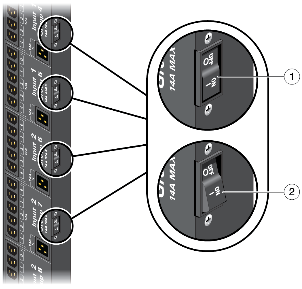
When switched on, a circuit breaker lies flush with the side of the PDU, as No. 1 shows in the following illustration. No. 2 shows the circuit breaker in the off position.

-
For SPARC M8-8 and SPARC M7-8 servers, switch on the circuit breakers
as follows:
-
Continue the installation by monitoring LEDs on the server.
See Monitor LEDs.