Internal
Component Locations
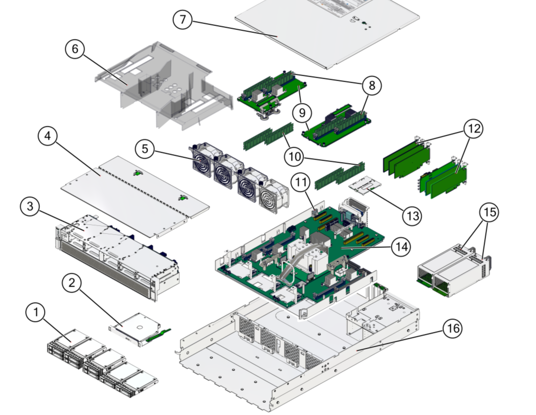
The following figure identifies the replaceable component locations.

|
|
|
|
1 |
Drives (eight drive configuration in this example) |
/SYS/DBP/HDD0 (lower left)
/SYS/DBP/HDD1
/SYS/DBP/HDD2 or /SYS/DBP/NVME0
/SYS/DBP/HDD3 or /SYS/DBP/NVME1
/SYS/DBP/HDD4 or /SYS/DBP/NVME2
/SYS/DBP/HDD5 or /SYS/DBP/NVME3
/SYS/DBP/HDD6
/SYS/DBP/HDD7 (right) |
|
3 |
Drive backplane (on drive cage) |
/SYS/DBP |
|
|
4
|
Fan module cover
|
|
|
5 |
Fan modules |
As viewed from front of server:
/SYS/MB/FM0 (left)
/SYS/MB/FM1 (left center)
/SYS/MB/FM2 (right center)
/SYS/MB/FM3 (right) |
|
|
6
|
Air baffle
|
|
|
|
7
|
Top cover
|
|
|
|
8
|
DIMMs
|
/SYS/MB/CMP[0-1]/MCU[0-1]/CH[0-1]/D[0-1]
|
|
11 |
Battery |
/SYS/MB/BAT |
|
12 |
PCIe cards |
/SYS/MB/PCIE1
/SYS/MB/PCIE2
/SYS/MB/PCIE3
/SYS/MB/PCIE4
/SYS/MB/PCIE5
/SYS/MB/PCIE6
/SYS/MB/PCIE7 (internal PCIe card) |
|
14 |
Motherboard |
/SYS/MB |
|
14 |
Processor chip (replaceable only by replacing the motherboard)
|
/SYS/MB/CMP[0-1] |
|
|
15
|
Power supplies |
/SYS/PS0 (outer)
/SYS/PS1 (inner) |
|
|
16
|
Chassis
|
|
|
|
|
eUSB drive
|
/SYS/MB/EUSB_DISK |
|
|

