JavaScript is required to for searching.
Skip Navigation Links
Exit Print View
Netra SPARC T3-1BA Blade Server User’s Guide
search filter icon
search icon

Document Information

Using This Documentation

UNIX Commands

Shell Prompts

Related Documentation

Documentation, Support, and Training

Evaluating Product Compatibility

Evaluating the Blade Server

Features

Front and Side Panels

Form-Factor Physical Characteristics

Block Diagram

SPARC T3 Processor

Memory Support

Service Processor

Networking and I/O

IPMC

IPMB

FPGA

ARTM Support

Hot-Swap Support

Ports and Connectors

System Watchdog Timers

Warranty and Technical Support

Qualifying Your System

System Configurations

System Requirements and Options

Installing Optional Components

Install an ARTM

Install Compact Flash

Install Onboard Memory

Installing the Blade Server

Preparing to Install the Blade Server

Environmental Requirements

Power and Thermal Distribution

Required Cooling and Blade Impedance Curve

Tools and Materials Needed

Local Network IP Addresses and Host Names

Safety Requirements

Upgrade the Fan Trays

Installing the Blade Server

Unpack the Blade Server

Install Optional Components

Connect the External I/O Cables

Connect Cables to a System Console Running the Oracle Solaris OS

Connect Cables to a System Console Not Running Oracle Solaris OS

Insert and Latch the Blade Server

Operating System and Patches

Software and Firmware Upgrades

Administering the System

Software and Firmware Upgrades

Firmware and Blade Server Management

Creating a Boot Disk Server and Adding Clients

Create a Boot Server for Diskless Clients

Add Diskless Clients

Connect Hosts to LAN

Compact Flash Formatting for the Oracle Solaris OS

Automatic Power-Off Events

Performing a Server Recovery

Administering Configurations

ShMM CLI and Commands

Electronic Blade Server ID

View Blade ID

View Midplane FRU Information

Change the OOS LED Color

Multiplex Configuration of Zones 2 and 3

Management Port Routing

Configuring Ports and Pins

Front Connectors

On-Board Connectors

Midplane Connectors

Advanced Rear Transition Module Connectors (Zone 3)

Administering the Network

Locate Base MAC Address on Blade Server

Configuring and Using Serial Over LAN

Log In to Oracle ILOM

Servicing the Blade Server

LEDs and Status Indicators

Reset the Blade Server

Replacing a Blade Server

Shut Down OS and Deactivate the Blade Server

Power Off and Remove the Blade Server

Removing Optional Components

Power Off and Remove an ARTM

Remove a Compact Flash Card

Remove Onboard Memory

Replace a TOD Clock Battery

Return a Blade Server

Part Number, Serial Number, and MAC Address Label Locations

Programming the Blade Server

Programmable Devices

Sensors

OEM and IPMI Commands

Glossary

Index

Front Connectors

The front panel has the following connectors, as shown in the following figure:

Figure 7 Ports on the Blade Server

Figure showing ports on the blade server.

Figure Legend

1 Serial port

2 Ethernet port

3 USB ports

Ethernet Port

The Ethernet connector is an RJ-45 connector. The controller autonegotiates to either 10 BASE-T, 100 BASE-T, or 1000 BASE-T.
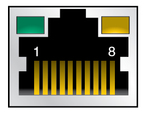
Figure showing Ethernet port connectors.

See the following table for the Ethernet port pin assignments.

Pin
Signal Name
Pin
Signal Name
1
BI_DA+
5
BI_DC-
2
BI_DA-
6
BI_DB-
3
BI_DB+
7
BI_DD+
4
BI_DC-
8
BI_DD-
USB Ports

The following figure shows the connectors for the front panel USB ports.
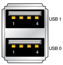
Figure showing USB port connectors.

The following table lists the pin assignments.

Pin
Signal Name
Pin
Signal Name
A1
+5 V
B1
+5 V
A2
USB2-
B2
USB3-
A3
USB2+
B3
USB3+
A4
Ground
B4
Ground
Serial Port

The following figure shows the connectors for the front panel serial port.

Figure 8 Serial Port Connector
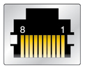
Figure showing serial port connector.

The following table lists the pin assignments.

Pin
Signal Name
Pin
Signal Name
1
RTS
5
GND
2
DTR
6
RXD
3
TXD
7
DSR
4
GND
8
CTS