| Skip Navigation Links | |
| Exit Print View | |

|
Netra SPARC T3-1BA Blade Server User’s Guide |
Documentation, Support, and Training
Evaluating Product Compatibility
Form-Factor Physical Characteristics
Warranty and Technical Support
System Requirements and Options
Installing Optional Components
Preparing to Install the Blade Server
Power and Thermal Distribution
Required Cooling and Blade Impedance Curve
Local Network IP Addresses and Host Names
Connect the External I/O Cables
Connect Cables to a System Console Running the Oracle Solaris OS
Connect Cables to a System Console Not Running Oracle Solaris OS
Insert and Latch the Blade Server
Software and Firmware Upgrades
Software and Firmware Upgrades
Firmware and Blade Server Management
Creating a Boot Disk Server and Adding Clients
Create a Boot Server for Diskless Clients
Compact Flash Formatting for the Oracle Solaris OS
Multiplex Configuration of Zones 2 and 3
Advanced Rear Transition Module Connectors (Zone 3)
Locate Base MAC Address on Blade Server
Configuring and Using Serial Over LAN
Shut Down OS and Deactivate the Blade Server
Power Off and Remove the Blade Server
The midplane has the following connectors, as shown in the following figure.
Figure 9 Midplane Connectors

Figure Legend
1 Power connectors (Zone 1)
2 Data transport connectors (Zone 2)
3 Data transport connectors (Zone 2)
4 ARTM connectors (Zone 3)
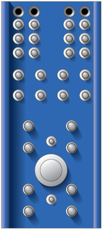
The blade server uses a 34-pin Positronic connector as the Zone 1 power distribution connector, as shown in the following figure.

Zone 1 provides the support for the following signals:
2 -48 VDC power feeds (four signals each; eight signals total)
2 IPMB ports (two signals each; four signals total)
Geographic address (eight signals)
2 ground pins
12 unpopulated pins
The analog test and ring voltage pins are left unconnected.
For pin assignments, refer to the PICMG 3.0 and PICMG 3.1 specifications.
The data transport connectors support 40 signal pairs, providing 200 differential pairs for a PICMG 3.0 blade server to establish connectivity with up to 15 other blade servers through a common midplane. The J carrier is on the motherboard and the mating P carrier is on the midplane.
Front connectors are labeled J20 to J24, and midplane connectors are labeled P20 to P24, with both J20 and P20 being at the top of Zone 2. The front connector is a right angle connector and contains female contacts. The midplane contains male contacts.
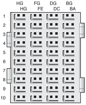
On the blade server, Zone 2 consists of two 120-pin HM-Zd connectors, labeled J20 and J23, with 40 differential pairs each, as shown in the following figure.

The Zone 2 connectors provide the following signals:
A Synchronization Clock Interface comprised of three separate and redundant clock buses.
Blade servers can act as clock sources (master mode) or can receive the Synchronization Clocks (slave mode) in J20.
An Update Channel Interface connecting the blade server to the midplane (4 differential signal pairs each; 16 signals total).
Connections are governed by the system Electronic Keying (e-Keying).
Two 10/100/1000BASE-T/TX Ethernet base fabric channels (four differential signal pairs each; 16 signals total)
Two 10-Gbit XAUI ports on the extended fabric (eight differential signal pairs each; 16 signals total)
Board and midplane slots might be equipped with a complete set or a subset of the five possible ZD connectors. For example, hub boards/slots might require all five connectors, and node slots might require only P23 and P20 connectors. Node boards might require only the J23 connector.
The BG, DG, FG, and HG (G for Ground) columns contain the ground shields for the four columns of differential pairs. All pins in the BG, DG, FG, and HG columns are connected to Logic Ground.
For pin assignments, refer to the PICMG 3.0 and PICMG 3.1 specifications.